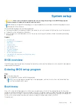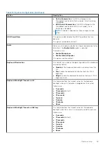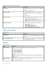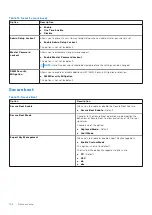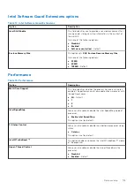
●
UEFI Boot:
○
Windows Boot Manager
●
●
Other Options:
○
BIOS Setup
○
BIOS Flash Update
○
Diagnostics
○
Change Boot Mode Settings
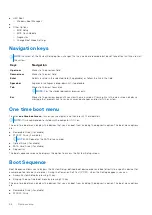
Navigation keys
NOTE:
For most of the System Setup options, changes that you make are recorded but do not take effect until you restart
the system.
Keys
Navigation
Up arrow
Moves to the previous field.
Down arrow
Moves to the next field.
Enter
Selects a value in the selected field (if applicable) or follow the link in the field.
Spacebar
Expands or collapses a drop-down list, if applicable.
Tab
Moves to the next focus area.
NOTE:
For the standard graphics browser only.
Esc
Moves to the previous page until you view the main screen. Pressing Esc in the main screen displays a
message that prompts you to save any unsaved changes and restarts the system.
One time boot menu
To enter
one time boot menu
, turn on your computer, and then press F12 immediately.
NOTE:
It is recommended to shutdown the computer if it is on.
The one-time boot menu displays the devices that you can boot from including the diagnostic option. The boot menu options
are:
●
Removable Drive (if available)
●
STXXXX Drive (if available)
NOTE:
XXX denotes the SATA drive number.
●
Optical Drive (if available)
●
SATA Hard Drive (if available)
●
Diagnostics
The boot sequence screen also displays the option to access the System Setup screen.
Boot Sequence
Boot Sequence allows you to bypass the System Setup–defined boot device order and boot directly to a specific device (for
example: optical drive or hard drive). During the Power-on Self Test (POST), when the Dell logo appears, you can:
●
Access System Setup by pressing F2 key
●
Bring up the one-time boot menu by pressing F12 key
The one-time boot menu displays the devices that you can boot from including the diagnostic option. The boot menu options
are:
●
Removable Drive (if available)
●
STXXXX Drive
96
System setup
Содержание Latitude 7400 2-in-1
Страница 15: ...Major components of your system 1 Base cover 2 Heatsink shield 3 Major components of your system 15 ...
Страница 24: ...4 Pry along the left right and bottom edges of the base 24 Removing and installing components ...
Страница 27: ...2 Press along the edges of the base cover until it clicks into place Removing and installing components 27 ...
Страница 28: ...3 Tighten the 10 captive screws to secure the base cover to the computer 28 Removing and installing components ...
Страница 43: ...5 Place the metal shield on the WWAN card Removing and installing components 43 ...
Страница 51: ...8 Adhere the Mylar sheet on the system board Removing and installing components 51 ...
Страница 56: ...4 Remove the metal foil from the heatsink shield 56 Removing and installing components ...
Страница 57: ...5 Remove the heatsink shield from the system board Removing and installing components 57 ...
Страница 60: ...3 Place the heatsink shield on the heatsink 60 Removing and installing components ...
Страница 61: ...4 Adhere the metal foils on the heatsink shield Removing and installing components 61 ...
Страница 87: ...8 Lift the keyboard off the palmrest assembly Removing and installing components 87 ...

