background image

Removing the coin-cell battery

WARNING: 

Before working inside your computer, read the safety information that shipped with your computer and follow the 

steps in 

Before working inside your computer

. After working inside your computer, follow the instructions in 

After working inside 

your computer

. For more safety best practices, see the Regulatory Compliance home page a

www.dell.com/

regulatory_compliance

.

CAUTION: 

Removing the coin-cell battery resets the BIOS setup program’s settings to default. It is recommended that you note 

the BIOS setup program’s settings before removing the coin-cell battery.

Prerequisites

Remove the 

optical drive

.

Remove the 

base cover

.

Procedure

CAUTION: 

Removing the coin-cell battery resets the BIOS setup program’s settings to default. Before removing the coin-cell 

battery, it is recommended to note the BIOS setup program’s settings.

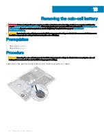
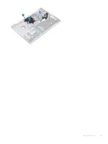
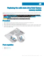
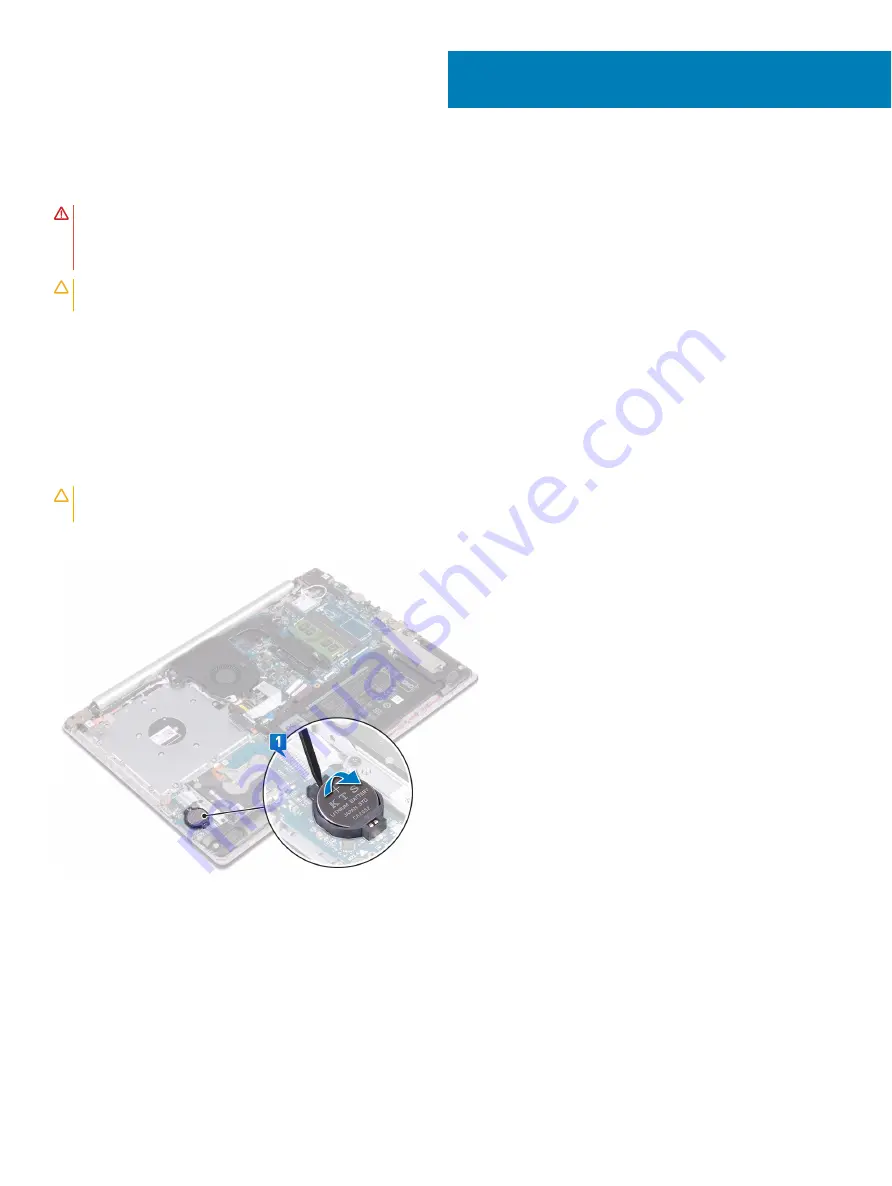
Using a plastic scribe, gently pry the coin-cell battery out of the battery socket on the I/O board.

18

36

Removing the coin-cell battery

Содержание Inspiron 3580

Страница 1: ...Inspiron 3580 Service Manual Regulatory Model P75F Regulatory Type P75F106 ...

Страница 2: ...amage to hardware or loss of data and tells you how to avoid the problem WARNING A WARNING indicates a potential for property damage personal injury or death 2018 Dell Inc or its subsidiaries All rights reserved Dell EMC and other trademarks are trademarks of Dell Inc or its subsidiaries Other trademarks may be trademarks of their respective owners 2018 12 Rev A00 ...

Страница 3: ...ment 13 4 Recommended tools 14 5 Screw list 15 6 Removing the optical drive 17 Procedure 17 7 Replacing the optical drive 19 Procedure 19 8 Removing the base cover 21 Prerequisites 21 Procedure 21 9 Replacing the base cover 23 Procedure 23 Post requisites 24 10 Removing the battery 25 Lithium ion battery precautions 25 Prerequisites 25 Procedure 25 11 Replacing the battery 27 Lithium ion battery p...

Страница 4: ...ure 35 Post requisites 35 18 Removing the coin cell battery 36 Prerequisites 36 Procedure 36 19 Replacing the coin cell battery 37 Procedure 37 Post requisites 37 20 Removing the fan 38 Prerequisites 38 Procedure 38 21 Replacing the fan 40 Procedure 40 Post requisites 41 22 Removing the solid state drive Intel Optane memory module 42 Prerequisites 42 Procedure 42 23 Replacing the solid state drive...

Страница 5: ...Post requisites 53 30 Removing the heat sink 54 Prerequisites 54 Procedure 54 31 Replacing the heat sink 55 Procedure 55 Post requisites 55 32 Removing the power adapter port 56 Prerequisites 56 Procedure 56 33 Replacing the power adapter port 57 Procedure 57 Post requisites 57 34 Removing the display assembly 58 Prerequisites 58 Procedure 58 35 Replacing the display assembly 61 Procedure 61 Post ...

Страница 6: ...g in the BIOS setup program 74 42 Removing the power button with fingerprint reader 75 Prerequisites 75 Procedure 75 43 Replacing the power button with fingerprint reader 77 Procedure 77 Post requisites 77 44 Removing the palm rest and keyboard assembly 79 Prerequisites 79 Procedure 79 45 Replacing the palm rest and keyboard assembly 81 Procedure 81 Post requisites 81 46 Removing the display bezel...

Страница 7: ...ay cable 93 Prerequisites 93 Procedure 93 55 Replacing the display cable 94 Procedure 94 Post requisites 94 56 Removing the display back cover and antenna assembly 95 Prerequisites 95 Procedure 95 57 Replacing the display back cover and antenna assembly 96 Procedure 96 Post requisites 96 58 Device drivers 97 Intel Chipset Software Installation Utility 97 Video drivers 97 Intel Serial IO driver 97 ...

Страница 8: ...ooting 105 Flashing the BIOS 105 Flashing BIOS USB key 105 Enhanced Pre Boot System Assessment ePSA diagnostics 105 Running the ePSA diagnostics 106 System diagnostic lights 106 Enabling Intel Optane memory 107 Disabling Intel Optane memory 107 WiFi power cycle 107 Flea power release 108 61 Getting help and contacting Dell 109 Self help resources 109 Contacting Dell 109 8 Contents ...

Страница 9: ... Start Power Shut down NOTE If you are using a different operating system see the documentation of your operating system for shut down instructions 3 Disconnect your computer and all attached devices from their electrical outlets 4 Disconnect all attached network devices and peripherals such as keyboard mouse and monitor from your computer 5 Remove any media card and optical disc from your compute...

Страница 10: ...y screws remain inside your computer 2 Connect any external devices peripherals or cables you removed before working on your computer 3 Replace any media cards discs or any other parts that you removed before working on your computer 4 Connect your computer and all attached devices to their electrical outlets 5 Turn on your computer 2 10 After working inside your computer ...

Страница 11: ... concern when you handle electronic components especially sensitive components such as expansion cards processors memory DIMMs and system boards Very slight charges can damage circuits in ways that may not be obvious such as intermittent problems or a shortened product life span As the industry pushes for lower power requirements and increased density ESD protection is an increasing concern Due to...

Страница 12: ...egional office to find out if they have one To perform the test plug the wrist strap s bonding wire into the tester while it is strapped to your wrist and push the button to test A green LED is lit if the test is successful a red LED is lit and an alarm sounds if the test fails Insulator Elements It is critical to keep ESD sensitive devices such as plastic heat sink casings away from internal part...

Страница 13: ... mechanical lifting device 1 Get a firm balanced footing Keep your feet apart for a stable base and point your toes out 2 Tighten stomach muscles Abdominal muscles support your spine when you lift offsetting the force of the load 3 Lift with your legs not your back 4 Keep the load close The closer it is to your spine the less force it exerts on your back 5 Keep your back upright whether lifting or...

Страница 14: ...Recommended tools The procedures in this document may require the following tools Philips screwdriver 1 Flat head screwdriver Plastic scribe 4 14 Recommended tools ...

Страница 15: ... list Component Secured to Screw type Quantity Screw image Base cover Palm rest and keyboard assembly M2x2 2 Base cover Palm rest and keyboard assembly M2x4 1 Base cover Palm rest and keyboard assembly M2 5x7 6 NOTE Screw color may vary depending on the configuration ordered Battery Palm rest and keyboard assembly M2x3 4 Display panel Display back cover and antenna assembly M2x2 4 Fan Palm rest an...

Страница 16: ...ard assembly M2x2 Big Head 1 Power adapter port Palm rest and keyboard assembly M2x3 1 Power button board Palm rest and keyboard assembly M2x2 1 Power button with fingerprint reader optional Palm rest and keyboard assembly M2x2 1 Solid state drive Intel Optane Palm rest and keyboard assembly M2x2 2 1 System board Palm rest and keyboard assembly M2x4 1 Touchpad Palm rest and keyboard assembly M2x2 ...

Страница 17: ...edure NOTE Applicable only for computers that are shipped with optical drive 1 Remove the screw M2x2 that secures the optical drive assembly to the base cover 2 Using a screwdriver push the optical drive through the slot to release the optical drive assembly out of the optical drive bay 3 Slide the optical drive assembly out of the optical drive bay 4 Remove the two screws M2x3 that secure the opt...

Страница 18: ...18 Removing the optical drive ...

Страница 19: ...atory_compliance Procedure NOTE Applicable only for computers that are shipped with optical drive 1 Align the tabs on the optical drive bezel with the slots on the optical drive and snap the optical drive bezel into place 2 Align the screw holes on the optical drive bracket with the screw holes on the optical drive 3 Replace the two screws M2x3 that secure the optical drive bracket to the optical ...

Страница 20: ...20 Replacing the optical drive ...

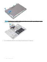
Страница 21: ... regulatory_compliance Prerequisites Remove the optical drive Procedure 1 Loosen the three captive screws on the base cover 2 Remove the screw M2x4 that secures the base cover to the palm rest and keyboard assembly 3 Remove the two screws M2x2 that secure the base cover to the palm rest and keyboard assembly 4 Remove the six screws M2 5x7 that secure the base cover to the palm rest and keyboard as...

Страница 22: ... if you want to further remove any other component from your computer 7 Disconnect the battery cable from the system board 8 Press and hold the power button for 5 seconds to ground the computer and drain the flea power 22 Removing the base cover ...

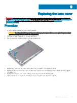
Страница 23: ...adapter port do not press the base cover against the power adapter port when you snap the base cover to the computer base 2 Place the base cover on the palm rest and keyboard assembly 3 Snap the base cover into place starting from the power adapter port 4 Replace the six screws M2 5x7 that secure the base cover to the palm rest and keyboard assembly 5 Replace the two screws M2x2 that secure the ba...

Страница 24: ...Post requisites Replace the optical drive 24 Replacing the base cover ...

Страница 25: ...the battery with foreign objects Do not expose the battery to high temperatures or disassemble battery packs and cells Do not apply pressure to the surface of the battery Do not bend the battery Do not use tools of any kind to pry on or against the battery If a battery gets stuck in a device as a result of swelling do not try to free it as puncturing bending or crushing a Lithium ion battery can b...

Страница 26: ...26 Removing the battery ...

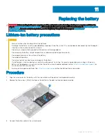
Страница 27: ...with foreign objects Do not expose the battery to high temperatures or disassemble battery packs and cells Do not apply pressure to the surface of the battery Do not bend the battery Do not use tools of any kind to pry on or against the battery If a battery gets stuck in a device as a result of swelling do not try to free it as puncturing bending or crushing a Lithium ion battery can be dangerous ...

Страница 28: ...Post requisites 1 Replace the base cover 2 Replace the optical drive 28 Replacing the battery ...

Страница 29: ...side your computer For more safety best practices see the Regulatory Compliance home page at www dell com regulatory_compliance Prerequisites 1 Remove the optical drive 2 Remove the base cover Procedure 1 Locate the memory module on your computer 2 Use your fingertips to carefully spread apart the securing clips on each end of the memory module slot until the memory module pops up 3 Remove the mem...

Страница 30: ...or more safety best practices see the Regulatory Compliance home page at www dell com regulatory_compliance Procedure 1 Align the notch on the memory module with the tab on the memory module slot 2 Slide the memory module firmly into the slot at an angle 3 Press the memory module down until it clicks into place NOTE If you do not hear the click remove the memory module and reinstall it Post requis...

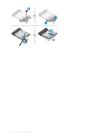
Страница 31: ...ee the Regulatory Compliance home page at www dell com regulatory_compliance Prerequisites 1 Remove the optical drive 2 Remove the base cover Procedure 1 Locate the wireless card on your computer 2 Remove the screw M2x3 that secures the wireless card bracket to the system board 3 Slide and remove the wireless card bracket from the wireless card 4 Using a plastic scribe disconnect the antenna cable...

Страница 32: ...32 Removing the wireless card ...

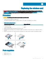
Страница 33: ... to the wireless card The following table provides the antenna cable color scheme for the wireless card supported by your computer Table 2 Antenna cable color scheme Connectors on the wireless card Antenna cable color Main white triangle White Auxiliary black triangle Black 2 Slide and replace the wireless card bracket on the wireless card 3 Align the notch on the wireless card with the tab on the...

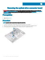
Страница 34: ...mpliance home page at www dell com regulatory_compliance Prerequisites 1 Remove the optical drive 2 Remove the base cover Procedure NOTE Applicable only for computers that are shipped with optical drive 1 Lift the latch and disconnect the optical drive connector board cable from the system board 2 Remove the screw M2x2 that secures the optical drive connector board to the palm rest and keyboard as...

Страница 35: ...tices see the Regulatory Compliance home page at www dell com regulatory_compliance Procedure 1 Align the screw hole on the optical drive connector board with the screw hole on the palm rest and keyboard assembly 2 Replace the screw M2x2 that secures the optical drive connector board to the palm rest and keyboard assembly 3 Connect the optical drive connector board cable to the system board and cl...

Страница 36: ...nce CAUTION Removing the coin cell battery resets the BIOS setup program s settings to default It is recommended that you note the BIOS setup program s settings before removing the coin cell battery Prerequisites 1 Remove the optical drive 2 Remove the base cover Procedure CAUTION Removing the coin cell battery resets the BIOS setup program s settings to default Before removing the coin cell batte...

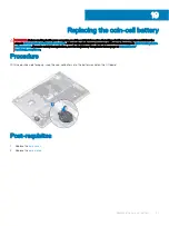
Страница 37: ... inside your computer follow the instructions in After working inside your computer For more safety best practices see the Regulatory Compliance home page at www dell com regulatory_compliance Procedure With the positive side facing up snap the coin cell battery into the battery socket on the I O board Post requisites 1 Replace the base cover 2 Replace the optical drive 19 Replacing the coin cell ...

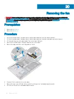
Страница 38: ...1 Lift the latch and disconnect the optical drive connector board cable from the system board Optional 2 Lift the latch and disconnect the optical drive connector board cable from the optical drive board connector Optional 3 Lift the optical drive connector board cable off the system board Optional 4 Open the latch and disconnect the display cable from the system board 5 Remove the display cable f...

Страница 39: ...Removing the fan 39 ...

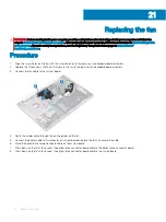
Страница 40: ...n to the palm rest and keyboard board assembly 2 Replace the three screws M2 5x5 that secure the fan to the palm rest and keyboard board assembly 3 Connect the fan cable to the system board 4 Route the display cable through the routing guides on the fan 5 Connect the display cable to its connector on system board and close the latch to secure the cable 6 Place the optical drive connector board cab...

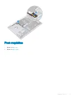
Страница 41: ...Post requisites 1 Replace the base cover 2 Replace the optical drive Replacing the fan 41 ...

Страница 42: ...ry_compliance Prerequisites 1 Remove the optical drive 2 Remove the base cover Procedure 1 Loosen the two captive screws that secure the solid state drive shield Intel Optane shield and solid state drive Intel Optane to the palm rest and keyboard assembly NOTE solid state drive shield Intel Optane shield is available only on computers shipped with NVMe solid state drive Intel Optane In computers s...

Страница 43: ...ww dell com regulatory_compliance CAUTION Solid state drives are fragile Exercise care when handling the solid state drive Procedure 1 Align the notch on the solid state drive Intel Optane with the tab on the solid state drive Intel Optane slot 2 Slide the solid state drive Intel Optane into the solid state drive Intel Optane slot 3 Align the screw holes on the solid state drive shield Intel Optan...

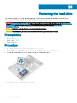
Страница 44: ...ty best practices see the Regulatory Compliance home page at www dell com regulatory_compliance CAUTION Hard drives are fragile Exercise care when handling the hard drive CAUTION To avoid data loss do not remove the hard drive while the computer is in sleep or on state Prerequisites 1 Remove the optical drive 2 Remove the base cover 3 Remove the battery Procedure 1 Open the latch and disconnect th...

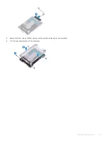
Страница 45: ...5 Remove the four screws M3x3 that secure the hard drive bracket to the hard drive 6 Lift the hard drive bracket off the hard drive Removing the hard drive 45 ...

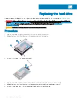
Страница 46: ...e at www dell com regulatory_compliance CAUTION Hard drives are fragile Exercise care when handling the hard drive Procedure 1 Align the screw holes on the hard drive bracket with the screw holes on the hard drive 2 Replace the four screws M3x3 that secure the hard drive bracket to the hard drive 3 Connect the interposer to the hard drive assembly 4 Align the screw holes on the hard drive assembly...

Страница 47: ...Post requisites 1 Replace the battery 2 Replace the base cover 3 Replace the optical drive Replacing the hard drive 47 ...

Страница 48: ...isites 1 Remove the optical drive 2 Remove the base cover 3 Remove the battery Procedure 1 Open the latch and disconnect the hard drive cable from the system board 2 Open the latch and disconnect the touchpad cable from the system board 3 Open the latch and disconnect the keyboard back light cable from the system board 4 Gently peel the tape that secures the touchpad to the palm rest and keyboard ...

Страница 49: ...Removing the touchpad 49 ...

Страница 50: ...keyboard assembly and the gap on either sides of the touchpad is equal 1 Slide and place the touchpad into the slot on the palm rest and keyboard assembly 2 Replace the four screws M2x2 that secure the touchpad to the palm rest and keyboard assembly 3 Adhere the tape that secures the touchpad to the palm rest and keyboard assembly 4 Slide the hard drive cable into the connector on the system board...

Страница 51: ...Post requisites 1 Replace the battery 2 Replace the base cover 3 Replace the optical drive Replacing the touchpad 51 ...

Страница 52: ...gulatory Compliance home page at www dell com regulatory_compliance Prerequisites 1 Remove the optical drive 2 Remove the base cover 3 Remove the solid state drive Intel Optane Procedure 1 Disconnect the speaker cable from the system board and lift the right speaker off the palm rest and keyboard assembly 2 Note the speaker cable routing and remove it from the routing guides on palm rest and key b...

Страница 53: ...ory_compliance Procedure NOTE If the rubber grommets are pushed out when removing the speakers push them back in before replacing the speakers 1 Using the alignment posts and rubber grommets place the left speakers in the slots on the palm rest and keyboard assembly 2 Route the speaker cable through the routing guides on the palm rest and keyboard assembly and replace the right speaker 3 Connect t...

Страница 54: ...ory_compliance WARNING The heat sink may become hot during normal operation Allow sufficient time for the heat sink to cool before you touch it CAUTION For maximum cooling of the processor do not touch the heat transfer areas on the heat sink The oils in your skin can reduce the heat transfer capability of the thermal grease Prerequisites 1 Remove the optical drive 2 Remove the base cover Procedur...

Страница 55: ... CAUTION Incorrect alignment of the heat sink can damage the system board and processor NOTE If either the system board or the heat sink is replaced use the thermal pad provided in the kit to ensure that thermal conductivity is achieved Procedure 1 Place the heat sink on the system board and align the screw holes on the heat sink with the screw holes on the system board 2 Tighten the captive screw...

Страница 56: ...ove the optical drive 2 Remove the base cover 3 Remove the wireless card Procedure 1 Remove the three screws M2 5x5 that secure the right hinge to the system board and palm rest assembly 2 Lift the right hinge 3 Disconnect the power adapter port cable from the system board 4 Note the power adapter port cable routing and remove it from the routing guides on the palm rest and keyboard assembly 5 Rem...

Страница 57: ...e screw hole on the power adapter port with the screw hole on the palm rest and keyboard assembly 2 Replace the screw M2x2 that secures the power adapter port to the palm rest and keyboard assembly 3 Route the power adapter port cable through the routing guides on the palm rest and keyboard assembly 4 Connect the power adapter port cable to the system board 5 Close the right hinge 6 Replace the th...

Страница 58: ...wireless card Procedure 1 Lift the latch and disconnect the optical drive connector board cable from the system board 2 Lift the latch and disconnect the optical drive connector board cable from the optical drive board connector 3 Lift the optical drive connector board cable off the system board 4 Open the latch and disconnect the display cable from the system board 5 Note the routing of the displ...

Страница 59: ... and keyboard assembly at an angle 9 Slide and remove the palm rest and keyboard assembly off the display assembly 10 After performing all the above steps you are left with display assembly Removing the display assembly 59 ...

Страница 60: ...60 Removing the display assembly ...

Страница 61: ...me page at www dell com regulatory_compliance Procedure NOTE Ensure that the hinges are opened to the maximum before replacing the display assembly on palm rest and keyboard assembly 1 Slide the palm rest and keyboard assembly at an angle 2 Close the palm rest and keyboard assembly 3 Using the alignment posts press the hinges down on the system board and the palm rest and keyboard assembly 4 Repla...

Страница 62: ...he optical drive connector board cable on the system board optional 8 Press down on the latch to connect the optical drive connector board cable to the optical drive connector board optional 9 Press down on the latch to connect the optical drive connector board cable to the system board Post requisites 1 Replace the wireless card 2 Replace the base cover 3 Replace the optical drive 62 Replacing th...

Страница 63: ...ell battery resets the BIOS setup program s settings to default Before removing the I O board along with the coin cell battery it is recommended to note the BIOS setup program s settings 1 Remove the optical drive 2 Remove the base cover 3 Remove the battery 4 Remove the hard drive Procedure 1 Open the latch and disconnect the I O board cable from the system board 2 Peel the I O board cable from t...

Страница 64: ...nce home page at www dell com regulatory_compliance Procedure 1 Using the alignment posts place the I O board on the palm rest and keyboard assembly 2 Replace the screw M2x4 that secures the I O board to the palm rest and keyboard assembly 3 Adhere the I O board cable to the palm rest and keyboard assembly 4 Connect the I O board cable to the system board and close the latch to secure the cable Po...

Страница 65: ...equisites 1 Remove the optical drive 2 Remove the base cover 3 Remove the fan Procedure 1 Remove the two screws M2 5x5 that secure the left hinge to palm rest and keyboard assembly 2 Open the left hinge 3 Open the latch and disconnect the power button board cable from the system board 4 Peel off the tape that secures the power button board to the palm rest and keyboard assembly 5 Remove the screw ...

Страница 66: ...66 Removing the power button board ...

Страница 67: ...e screw hole on the power button board with the screw hole on the palm rest and keyboard assembly 2 Replace the screw M2x3 that secures the power button board to the palm rest and keyboard assembly 3 Adhere the tape that secures the power button board to the palm rest and keyboard assembly 4 Slide the power button cable to the system board and close the latch to secure the cable 5 Close the left h...

Страница 68: ...Post requisites 1 Replace the fan 2 Replace the base cover 3 Replace the optical drive 68 Replacing the power button board ...

Страница 69: ...he memory modules 5 Remove the wireless card 6 Remove the solid state drive Intel Optane 7 Remove the fan 8 Remove the heat sink Procedure 1 Disconnect the power adapter port cable from the system board 2 Disconnect the speaker cable from the system board 3 Open the latch and disconnect the keyboard from the system board 4 Open the latch and disconnect the keyboard back light cable from the system...

Страница 70: ...e the right hinge to the system board 15 Open the right hinge 16 Remove the screw M2x4 that secures the system board to palm rest and keyboard assembly 17 Lift the system board off the palm rest and keyboard assembly 70 Removing the system board ...

Страница 71: ...Removing the system board 71 ...

Страница 72: ...he system board You must enter the Service Tag in the BIOS setup program after you replace the system board NOTE Replacing the system board removes any changes you have made to the BIOS using the BIOS setup program You must make the appropriate changes again after you replace the system board Procedure 1 Align the screw hole on the system board with the screw hole on the palm rest and keyboard ass...

Страница 73: ...ble into the connector on the system board and close the latch 11 Connect the speaker cable to the system board 12 Connect the power adapter port cable to the system board 13 Slide the power button board cable into the connector on the system board and close the latch 14 Open the latch and connect the display cable to the system board 15 Align the optical drive connector board cable to the connect...

Страница 74: ...e cover 8 Replace the optical drive Entering the Service Tag in the BIOS setup program 1 Turn on or restart your computer 2 Press F2 when the Dell logo is displayed to enter the BIOS setup program 3 Navigate to the Main tab and enter the Service Tag in the Service Tag Input field NOTE Service tag is the alphanumeric identifier located at the back side of your computer 74 Replacing the system board...

Страница 75: ...1 Remove the optical drive 2 Remove the base cover 3 Remove the battery 4 Remove the solid state drive Intel Optane 5 Remove the fan 6 Remove the heat sink 7 Remove the wireless card 8 Remove the power button board 9 Remove the system board Procedure 1 Peel the fingerprint reader cable off the palm rest and keyboard assembly 2 Remove the screw M2x2 that secures the power button with fingerprint re...

Страница 76: ...76 Removing the power button with fingerprint reader ...

Страница 77: ...t are shipped with fingerprint reader Procedure 1 Using the alignment posts align and place the power button with fingerprint reader on the palm rest and keyboard assembly 2 Replace the screw M2x2 that secures the power button with fingerprint reader to the palm rest and keyboard assembly 3 Adhere the fingerprint reader cable on the palm rest and keyboard assembly Post requisites 1 Replace the sys...

Страница 78: ...9 Replace the optical drive 78 Replacing the power button with fingerprint reader ...

Страница 79: ...he optical drive 2 Remove the base cover 3 Remove the battery 4 Remove the optical drive connector board 5 Remove the fan 6 Remove the heat sink 7 Remove the solid state drive Intel Optane 8 Remove the wireless card 9 Remove the speakers 10 Remove the hard drive 11 Remove the touchpad 12 Remove the power adapter port 13 Remove the display assembly 14 Remove the I O board 15 Remove the power button...

Страница 80: ...80 Removing the palm rest and keyboard assembly ...

Страница 81: ... safety best practices see the Regulatory Compliance home page at www dell com regulatory_compliance Procedure Place the palm rest and keyboard assembly on a flat surface Post requisites 1 Replace the power button with fingerprint reader optional 2 Replace the system board 3 Replace the power button board 4 Replace the I O board 5 Replace the display assembly 6 Replace the power adapter port 7 Rep...

Страница 82: ...solid state drive Intel Optane 12 Replace the heat sink 13 Replace the fan 14 Replace the optical drive connector board 15 Replace the battery 16 Replace the base cover 17 Replace the optical drive 82 Replacing the palm rest and keyboard assembly ...

Страница 83: ...er For more safety best practices see the Regulatory Compliance home page at www dell com regulatory_compliance Prerequisites 1 Remove the optical drive 2 Remove the base cover 3 Remove the wireless card 4 Remove the display assembly Procedure 1 Using a plastic scribe carefully pry up the display bezel from the top left outer edge of the display back cover and antenna assembly 2 Remove the display...

Страница 84: ...tions in After working inside your computer For more safety best practices see the Regulatory Compliance home page at www dell com regulatory_compliance Procedure Align the display bezel with the display back cover and antenna assembly and then gently snap the display bezel into place Post requisites 1 Replace the display assembly 2 Replace the wireless card 3 Replace the base cover 4 Replace the ...

Страница 85: ...best practices see the Regulatory Compliance home page at www dell com regulatory_compliance Prerequisites 1 Remove the optical drive 2 Remove the base cover 3 Remove the wireless card 4 Remove the display assembly 5 Remove the display bezel Procedure 1 Using a plastic scribe gently pry the camera off the display back cover and antenna assembly 2 Disconnect the camera cable from the camera module ...

Страница 86: ...re safety best practices see the Regulatory Compliance home page at www dell com regulatory_compliance Procedure 1 Align the camera module with the camera cable 2 Connect the camera cable to the camera module 3 Using the alignment post adhere the camera module to the display back cover and antenna assembly Post requisites 1 Replace the display bezel 2 Replace the display assembly 3 Replace the wir...

Страница 87: ...liance Prerequisites 1 Remove the optical drive 2 Remove the base cover 3 Remove the wireless card 4 Remove the display assembly 5 Remove the display bezel Procedure 1 Remove the four screws M2x2 that secure the display panel to the display back cover and antenna assembly 2 Lift the display panel and turn it over 3 Peel the tape adhering the display cable to the back of the display panel 4 Lift th...

Страница 88: ...88 Removing the display panel ...

Страница 89: ...pliance Procedure 1 Place the display panel on a flat and clean surface 2 Connect the display cable to the connector at the back of the display panel and close the latch to secure the cable 3 Adhere the tape that secures the display cable to the back of the display panel 4 Place the display panel on the display back cover and antenna assembly 5 Align the screw holes on the display panel with the s...

Страница 90: ...Post requisites 1 Replace the display bezel 2 Replace the display assembly 3 Replace the wireless card 4 Replace the base cover 5 Replace the optical drive 90 Replacing the display panel ...

Страница 91: ...e page at www dell com regulatory_compliance Prerequisites 1 Remove the optical drive 2 Remove the base cover 3 Remove the wireless card 4 Remove the display assembly 5 Remove the display bezel 6 Remove the display panel Procedure 1 Remove the eight screws M2 5x2 5 that secure the hinges to the display back cover and antenna assembly 2 Remove the two screws M2x2 that secure the hinge brackets to t...

Страница 92: ...egulatory_compliance Procedure 1 Align the screw holes on the hinges and brackets with the screw holes on the display back cover and antenna assembly 2 Replace the two screws M2x2 that secure the hinge plates to the display back cover and antenna assembly 3 Replace the eight screws M2 5x2 5 that secure the hinges to the display back cover and antenna assembly Post requisites 1 Replace the display ...

Страница 93: ... home page at www dell com regulatory_compliance Prerequisites 1 Remove the optical drive 2 Remove the base cover 3 Remove the wireless card 4 Remove the display assembly 5 Remove the display bezel 6 Remove the display panel 7 Remove the display hinges Procedure 1 Disconnect the camera cable from the camera module 2 Note the display cable routing and remove the cable from the routing guides on the...

Страница 94: ..._compliance Procedure 1 Route the display cable along the routing guides starting from the bottom of the display near the hinges 2 Route the rest of the display cable along the routing guides on the left side of the display back cover and antenna assembly 3 Slide the camera cable into the connector on the camera module to secure the cable Post requisites 1 Replace the display hinges 2 Replace the ...

Страница 95: ...ore safety best practices see the Regulatory Compliance home page at www dell com regulatory_compliance Prerequisites 1 Remove the optical drive 2 Remove the base cover 3 Remove the wireless card 4 Remove the display assembly 5 Remove the display bezel 6 Remove the camera 7 Remove the display panel 8 Remove the display hinges 9 Remove the display cable Procedure After performing all the above step...

Страница 96: ...or more safety best practices see the Regulatory Compliance home page at www dell com regulatory_compliance Procedure Place the display back cover and antenna assembly on a clean and flat surface Post requisites 1 Replace the display cable 2 Replace the display hinges 3 Replace the display panel 4 Replace the camera 5 Replace the display bezel 6 Replace the display assembly 7 Replace the wireless ...

Страница 97: ...l com support Intel Trusted Execution Engine Interface In the Device Manager check if the Intel Trusted Execution Engine Interface driver is installed Install the driver update from www dell com support Intel Virtual Button driver In the Device Manager check if the Intel Virtual Button driver is installed Install the driver updates from www dell com support Wireless and Bluetooth drivers In the De...

Страница 98: ...yboard is initialized This prompt can appear very quickly so you must watch for it and then press F2 If you press F2 before the F2 prompt this keystroke is lost If you wait too long and the operating system logo appears continue to wait until you see the desktop Then turn off your computer and try again Navigation keys NOTE For most of the System Setup options changes that you make are recorded bu...

Страница 99: ...Displays the Asset Tag of the computer Ownership Tag Displays the ownership tag of the computer Manufacture Date Displays the manufacture date of the computer Ownership Date Displays the ownership date of the computer Express Service Code Displays the express service code of the computer Memory Information Memory Installed Displays the total computer memory installed Memory Available Displays the ...

Страница 100: ...formation of the computer Bluetooth Device Displays the bluetooth device information of the computer Battery Information Displays the battery health information Boot Sequence Boot Sequence Displays the boot sequence Boot List Option Displays the available boot options Advanced Boot Options Enable Legacy Option ROMs Enable or disable the Legacy Option ROMs Enable Attempt Legacy Boot Enable or disab...

Страница 101: ...e the internal hard disk drive password Strong Password Enable or disable strong passwords Password Configuration Control the minimum and maximum number of characters allowed for Admin and System passwords Password Bypass Bypass the System Boot Password and the internal HDD password prompts during a system restart Password Change Enable or disable changes to the System and Hard Disk passwords when...

Страница 102: ...able or disable HyperThreading in the processor Default Enabled Power Management AC Behavior Enables the system to turn on automatically when AC power is supplied Enable Intel Speed Shift Technology Enable or disable Intel Speed Shift Technology Auto On Time Enable to set the computer to turn on automatically every day or on a preselected date and time This option can be configured only if the Aut...

Страница 103: ...ireless devices can be controlled by the Wireless Switch Wireless Device Enable Enable or disable internal wireless devices Table 11 System setup options Maintenance menu Maintenance Service Tag Display the system s Service Tag Asset Tag Create a system Asset Tag BIOS Downgrade Control flashing of the system firmware to previous revisions Data Wipe Enable to securely erase data from all internal s...

Страница 104: ...minute 5 Replace the coin cell battery 6 Connect the battery cable to the system board 7 Replace the base cover Clearing BIOS System Setup and System passwords To clear the system or BIOS passwords contact Dell technical support as described at www dell com contactdell NOTE For information on how to reset Windows or application passwords refer to the documentation accompanying Windows or your appl...

Страница 105: ...he BIOS setup program file to the bootable USB drive 4 Connect the bootable USB drive to the computer that needs the BIOS update 5 Restart the computer and press F12 when the Dell logo is displayed on the screen 6 Boot to the USB drive from the One Time Boot Menu 7 Type the BIOS setup program filename and press Enter 8 The BIOS Update Utility appears Follow the instructions on the screen to comple...

Страница 106: ...the battery has more than 5 percent charge Amber Computer is running on battery and the battery has less than 5 percent charge Off Power adapter is connected and the battery is fully charged Computer is running on battery and the battery has more than 5 percent charge Computer is in sleep state hibernation or turned off The power and battery status light blinks amber along with beep codes indicati...

Страница 107: ... Disabling Intel Optane memory CAUTION After disabling Intel Optane memory do not uninstall the driver for Intel Rapid Storage Technology as it will result in a blue screen error The Intel Rapid Storage Technology user interface can be removed without uninstalling the driver NOTE Disabling Intel Optane memory is required before removing the SATA storage device accelerated by the Intel Optane memor...

Страница 108: ...se Flea power is the residual static electricity that remains on the computer even after it has been powered off and the battery has been removed The following procedure provides the instructions on how to conduct flea power release 1 Turn off your computer 2 Disconnect the power adapter from your computer 3 Press and hold the power button for 15 seconds to drain the flea power 4 Connect the power...

Страница 109: ...related articles Learn and know the following information about your product Product specifications Operating system Setting up and using your product Data backup Troubleshooting and diagnostics Factory and system restore BIOS information See Me and My Dell at www dell com support manuals To locate the Me and My Dell relevant to your product identify your product through one of the following Selec...

Отзывы: