


16
About Your System
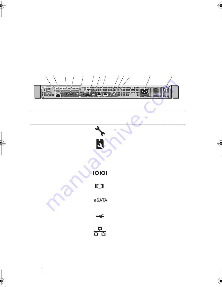
Back-Panel Features and Indicators
Figure 1-2 shows the controls, indicators, and connectors located on the
system's back panel.
Figure 1-2.
Back-Panel Features and Indicators
Item
Indicator, Button, or
Connector
Icon
Description
1
iDRAC6 Enterprise
port (optional)
Dedicated management port for the
optional iDRAC6 Enterprise card.
2
VFlash media slot
(optional)
Connects an external SD memory card
for the optional iDRAC6 Enterprise
card.
3
PCIe expansion card
slot
Connects a PCI Express expansion
card.
4
Serial connector
Connects a serial device to the system.
5
Video connector
Connects a VGA display to the system.
6
eSATA
Connects additional storage devices.
7
USB connectors (2)
Connects USB devices to the system.
The ports are USB 2.0-compliant.
8
Ethernet connectors
(2)
Embedded 10/100/1000 NIC
connectors.
1
2
4
13
5
6
7 8
9 10 11
12
3
book.book Page 16 Wednesday, August 12, 2009 4:51 PM
Содержание External OEMR R210
Страница 1: ...Dell PowerEdge R210 Systems Hardware Owner s Manual ...
Страница 9: ...Contents 11 7 Getting Help 133 Contacting Dell 133 Glossary 135 Index 145 ...
Страница 10: ...12 Contents ...
Страница 34: ...36 About Your System ...
Страница 56: ...58 Using the System Setup Program and UEFI Boot Manager ...
Страница 128: ...134 Getting Help ...
Страница 138: ...144 Glossary ...
Страница 143: ...Index 149 V VFlash media 93 video troubleshooting 110 W warning messages 34 wet system troubleshooting 112 ...
Страница 144: ...Index 150 ...