background image

Steps

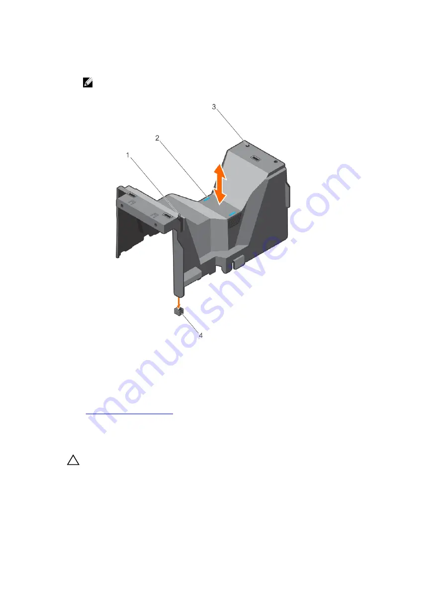
Holding the touch points, lift the cooling shroud from the system.

NOTE: Systems with x16 hard-drive backplanes use a different cooling shroud. To ensure 
proper cooling, always install the cooling shroud provided with your system.

Figure 17. Removing and installing the cooling shroud — 3.5 inch hard-drive system

1.

chassis intrusion switch

2. touch points (2)

3. slots (2)

4. chassis intrusion-switch connector on 

the system board

Related Links

Installing the cooling shroud

Installing the cooling shroud

Prerequisites

CAUTION: Many repairs may only be done by a certified service technician. You should only 
perform troubleshooting and simple repairs as authorized in your product documentation, or as 
directed by the online or telephone service and support team. Damage due to servicing that is 
not authorized by Dell is not covered by your warranty. Read and follow the safety instructions 
that came with the product.

62

Содержание E30S001

Страница 1: ...Dell PowerEdge T430 Owner s Manual Regulatory Model E30S Series Regulatory Type E30S001 ...

Страница 2: ...problem WARNING A WARNING indicates a potential for property damage personal injury or death Copyright 2014 Dell Inc All rights reserved This product is protected by U S and international copyright and intellectual property laws Dell and the Dell logo are trademarks of Dell Inc in the United States and or other jurisdictions All other marks and names mentioned herein may be trademarks of their res...

Страница 3: ...Setting up your system 27 Setting up and configuring the iDRAC IP address 27 Logging in to iDRAC 27 Installing the operating system 28 Managing your system remotely 28 Downloading and installing drivers and firmware 28 3 Pre operating system management applications 30 Navigation keys 30 About System Setup 30 Entering System Setup 31 System Setup Main Menu 31 System BIOS screen 31 System Informatio...

Страница 4: ...8 4 Installing and removing system components 49 Safety instructions 49 Before working inside your system 49 After working inside your system 49 Recommended tools 50 Front bezel optional 50 Installing the front bezel 50 Removing the front bezel 51 System feet 51 Removing the system feet 51 Installing the system feet 52 Caster wheels optional tower mode 53 Installing caster wheels 53 Removing caste...

Страница 5: ...rive backplane 77 Installing the hard drive backplane 82 Four slot hard drive blank 82 Removing a four slot hard drive blank 82 Installing a four slot hard drive blank 83 System memory 84 General memory module installation guidelines 86 Mode specific guidelines 86 Sample memory configurations 87 Removing memory modules 89 Installing memory modules 90 Cooling fans 92 Removing the internal cooling f...

Страница 6: ...Installing the power supply unit blank 122 Replacing the power supply divider 122 Non redundant AC power supply 123 Removing a non redundant AC power supply 124 Installing a non redundant AC power supply 125 Power interposer board 126 Removing the power interposer board 126 Installing the power interposer board 127 System battery 128 Replacing the system battery 128 Control panel assembly 129 Remo...

Страница 7: ...xternal connections 152 Troubleshooting the video subsystem 152 Troubleshooting a USB device 152 Troubleshooting iDRAC Direct USB XML configuration 153 Troubleshooting iDRAC Direct laptop connection 154 Troubleshooting a serial I O device 154 Troubleshooting a NIC 154 Troubleshooting a wet system 155 Troubleshooting a damaged system 156 Troubleshooting the system battery 156 Troubleshooting power ...

Страница 8: ...edded System Diagnostics from Boot Manager 166 Running the Embedded System Diagnostics from the Dell Lifecycle Controller 166 System diagnostic controls 167 8 Jumpers and connectors 168 System board connectors 168 System board jumper settings 170 Disabling a forgotten password 170 9 Technical Specifications 172 10 Getting help 178 Contacting Dell 178 Locating your system Service Tag 178 Quick Reso...

Страница 9: ...ocessor family up to 12 DIMMs and storage capacity of up to 16 hard drives SSDs The T430 is available in the following configurations System Configuration 3 5 inch hard drive system Up to four 3 5 inch cabled hard drives Up to eight 3 5 inch hot swappable hard drives 2 5 inch hard drive system Up to sixteen 2 5 inch hot swappable hard drives 9 ...

Страница 10: ...Front panel features and indicators Figure 1 Front panel features and indicators 2 5 inch hot swap hard drive chassis 10 ...

Страница 11: ...3 5 inch hot swap hard drive chassis Item Indicator button or connector Icon Description 1 Power on indicator power button The power on indicator lights when the system power is on The power button controls the power supply output to the system 11 ...

Страница 12: ...f the buttons is pressed again Press to toggle the system ID on and off If the system stops responding during POST press and hold the system ID button for more than five seconds to enter BIOS progress mode To reset iDRAC if not disabled in F2 iDRAC setup press and hold for more than 15 seconds 4 LCD menu buttons Allow you to navigate the control panel LCD menu 5 Information tag A slide out label p...

Страница 13: ...ring a system for conversion from tower mode to rack mode 9 USB connector Allows you to connect USB devices to the system This port is USB 3 0 compliant 10 Optical drive or tape drive bay Allows you to install optical drives or tape drives For more information on supported optical drives and tape drives see Optical drives and tape drives optional 11 Physical drives 3 5 inch hard drives and 2 5 inc...

Страница 14: ... 3 5 inch cabled hard drive chassis Item Indicator Button or Connector Icon Description 1 Power on indicator power button The power on indicator lights when the system power is on The power button controls the power supply output to the system 14 ...

Страница 15: ...e back flash until one of the buttons is pressed again Press to toggle the system ID on and off If the system stops responding during POST press and hold the system ID button for more than five seconds to enter BIOS progress mode To reset iDRAC if not disabled in F2 iDRAC setup press and hold for more than 15 seconds 4 Information tag A slide out label panel which contains system information such ...

Страница 16: ... messaging is turned off through the iDRAC utility the LCD panel or other tools Figure 4 LCD panel features Item Button Description 1 Left Moves the cursor back in one step increments 2 Select Selects the menu item highlighted by the cursor 3 Right Moves the cursor forward in one step increments During message scrolling Press once to increase scrolling speed Press again to stop Press again to retu...

Страница 17: ...tions and option items that can be set as the default on the Home screen View menu NOTE When you select an option in the View menu you must confirm the option before proceeding to the next action Option Description iDRAC IP Displays the IPv4 or IPv6 addresses for the iDRAC7 Addresses include DNS Primary and Secondary Gateway IP and Subnet IPv6 does not have Subnet MAC Displays the MAC addresses fo...

Страница 18: ...em experiences an electrical error for example voltage out of range or a failed power supply or voltage regulator See the System Event Log or system messages for the specific issue If it is due to a problem with the power supply check the LED on the power supply Re seat the power supply by removing and reinstalling it If the problem persists see Getting help Temperatur e indicator The indicator bl...

Страница 19: ...en two times per second Identifying drive or preparing for removal Off Drive ready for insertion or removal NOTE The drive status indicator remains off until all hard drives are initialized after the system is turned on Drives are not ready for insertion or removal during this time Blinks green amber and turns off Predicted drive failure Blinks amber four times per second Drive failed Blinks green...

Страница 20: ... indicators Figure 6 Back panel features and indicators Item Indicator button or connector Icon Description 1 Power supplies PSU1 and PSU2 Redundant power supply Up to two 495 W 750 W or 1100 W redundant AC power supplies 20 ...

Страница 21: ...Press to toggle the system ID on and off If the system stops responding during POST press and hold the system ID button for more than five seconds to enter the BIOS progress mode To reset iDRAC if not disabled in F2 iDRAC setup press and hold for more than 15 seconds 4 iDRAC port optional Dedicated management port on the iDRAC ports card 5 System identification connector Allows you to connect the ...

Страница 22: ... NIC is connected to a valid network at its maximum port speed 1 Gbps C Link indicator is yellow The NIC is connected to a valid network at less than its maximum port speed D Activity indicator is blinking green Network data is being sent or received Indicator codes for redundant power supply Each AC power supply has an illuminated translucent handle that indicates whether power is present or whet...

Страница 23: ...rmware by using Life cycle controller See Dell Lifecycle Controller User s Guide at dell com esmmanuals C Flashing green and turns off When hot adding a power supply unit the power supply handle flashes green five times at 4 Hz rate and turns off This indicates that there is a power supply mismatch with respect to efficiency feature set health status and supported voltage Replace the power supply ...

Страница 24: ...voltages they can output different wattages and trigger a mismatch CAUTION If two power supplies are used they must be of the same type and have the same maximum output power CAUTION Combining AC and DC power supplies is not supported and triggers a mismatch E Not lit Power is not connected Indicator codes for non redundant power supply Press the self diagnostic button to perform a quick health ch...

Страница 25: ...le Controller know the features use and troubleshoot Lifecycle Controller Dell Lifecycle Controller User s Guide at dell com esmmanuals Use Lifecycle Controller Remote Services Dell Lifecycle Controller Remote Services Quick Start Guide at dell com esmmanuals Set up use and troubleshoot OpenManage Server Administrator Dell OpenManage Server Administrator User s Guide at dell com openmanagemanuals ...

Страница 26: ...26 ...

Страница 27: ...can set up the Integrated Dell Remote Access Controller iDRAC IP address by using one of the following interfaces iDRAC Settings utility Lifecycle Controller Dell OpenManage Deployment Toolkit Server LCD panel You can configure iDRAC IP address by using the following interfaces iDRAC Web interface For more information see the Integrated Dell Remote Access Controller User s Guide Remote Access Cont...

Страница 28: ... To perform out of band systems management using iDRAC you must configure iDRAC for remote accessibility set up the management station and managed system and configure the supported Web browsers For more information see the Integrated Dell Remote Access Controller User s Guide at dell com esmmanuals You can also remotely monitor and manage the server by using the Dell OpenManage Server Administrat...

Страница 29: ...4 Download the drivers you require to a diskette drive USB drive CD or DVD 29 ...

Страница 30: ...ext screen Up arrow Moves to the previous field Down arrow Moves to the next field Enter Enables you to type a value in the selected field if applicable or follow the link in the field Spacebar Expands or collapses a drop down list if applicable Tab Moves to the next focus area NOTE This feature is applicable for the standard graphical browser only Esc Moves to the previous page until you view the...

Страница 31: ...s Controller User s Guide at dell com esmmanuals Device Settings Enables you to configure device settings System BIOS screen By using the System BIOS screen you can view the BIOS settings as well as edit specific functions such as Boot Order System Password Setup Password setting the RAID mode and enabling or disabling USB ports In the System Setup Main Menu click System BIOS Menu Item Description...

Страница 32: ... Tag System Manufacturer Displays the name of the system manufacturer System Manufacturer Contact Information Displays the contact information of the system manufacturer System CPLD Version Displays the current revision of the system CPLD firmware UEFI Compliance Version Displays the system firmware UEFI compliance level Memory Settings screen You can use the Memory Settings screen to view all the...

Страница 33: ...splays all the logical processors If this option is set to Disabled the BIOS displays only one logical processor per core By default the Logical Processor option is set to Enabled Alternate RTID Requestor Transaction ID Setting Enables you to allocate more RTIDs to the remote socket thereby increasing cache performance between the sockets or easing work in normal mode for NUMA By default the Alter...

Страница 34: ...ocessor Bus Speed Displays the bus speed of the processor NOTE The processor bus speed option displays only when both processors are installed Processor 1 NOTE Depending on the number of installed CPUs there may be up to two processor listings The following settings are displayed for each processor installed in the system Family Model Stepping Displays the family model and stepping of the processo...

Страница 35: ...SATA settings in ATA mode set this field to Auto to enable BIOS support Set it to OFF to turn off BIOS support For AHCI mode or RAID mode BIOS always enables support Model Displays the drive model of the selected device Drive Type Displays the type of drive attached to the SATA port Capacity Displays the total capacity of the hard drive The field is undefined for removable media devices such as op...

Страница 36: ...ia devices such as optical drives Port H Sets the drive type of the selected device For Embedded SATA settings in ATA mode set this field to Auto to enable BIOS support Set it to OFF to turn off BIOS support For AHCI mode or RAID mode BIOS always enables support Model Displays the drive model of the selected device Drive Type Displays the type of drive attached to the SATA port Capacity Displays t...

Страница 37: ...Boot Sequence Retry feature If this field is enabled and the system fails to boot the system reattempts the boot sequence after 30 seconds By default the Boot Sequence Retry option is set to Enabled Hard Disk Failover Specifies which devices in the Hard Disk Drive Sequence are attempted in the boot sequence When the option is Disabled only the first hard disk device in the list is attempted to boo...

Страница 38: ...ure this function using the NIC management utilities of the system I OAT DMA Engine Allows you to enable or disable the I OAT option Enable only if the hardware and software supports the feature Embedded Video Controller Allows you to enable or disable the Embedded Video Controller By default the embedded video controller is Enabled If the Embedded Video Controller is the only display capability i...

Страница 39: ... MUX setting can independently be changed in iDRAC Therefore loading the BIOS default settings from within the BIOS setup utility may not always revert this setting to the default setting of Serial Device 1 External Serial Connector You can associate the External Serial Connector to Serial Device 1 Serial Device 2 or the Remote Access Device using this field NOTE Only Serial Device 2 can be used f...

Страница 40: ...fficient Turbo EET is a mode of operation where a processor s core frequency is adjusted within the turbo range based on workload C1E Enables or disables the processor to switch to a minimum performance state when it is idle By default the C1E option is set to Enabled C States Enables or disables the processor to operate in all available power states By default the C States option is set to Enable...

Страница 41: ...ing encryption and decryption using the Advanced Encryption Standard Instruction Set and is set to Enabled by default System Password Sets the system password This option is set to Enabled by default and is read only if the password jumper is not installed in the system Setup Password Sets the setup password This option is read only if the password jumper is not installed in the system Password St...

Страница 42: ...rolled selected UEFI variables are protected in the environment and new UEFI boot entries are forced to be at the end of the current boot order Secure Boot Enables Secure Boot where the BIOS authenticates each pre boot image using the certificates in the Secure Boot Policy Secure Boot is disabled by default Secure Boot Policy When Secure Boot policy is Standard the BIOS uses the system manufacture...

Страница 43: ... errors Load Legacy Video Option ROM Enables you to determine whether the system BIOS loads the legacy video INT 10H option ROM from the video controller Selecting Enabled in the operating system does not support UEFI video output standards This field is only for UEFI boot mode You cannot set this to Enabled if UEFI Secure Boot mode is enabled About Boot Manager Boot Manager enables you to add del...

Страница 44: ...ry if you have selected BIOS for Boot Mode 1 In the System Setup Main Menu click System BIOS Boot Settings 2 Click Boot Option Settings Boot Sequence 3 Use the arrow keys to select a boot device and use the and keys to move the device down or up in the order 4 Click Exit click Yes to save the settings on exit Choosing the system boot mode System Setup enables you to specify the boot mode for insta...

Страница 45: ...tup Password follow the steps below Steps 1 To enter System Setup press F2 immediately after a power on or restart 2 From the System Setup Main Menu select System BIOS and press Enter The System BIOS screen is displayed 3 On the System BIOS screen select System Security and press Enter The System Security screen is displayed 4 On the System Security screen verify that Password Status is Unlocked 5...

Страница 46: ... system password and setup password Prerequisites Ensure that the Password jumper is set to enabled and the Password Status is Unlocked before attempting to delete or change the existing System and or Setup password You cannot delete or change an existing System or Setup password if the Password Status is Locked Steps 1 To enter System Setup press F2 immediately after a power on or restart 2 From ...

Страница 47: ...s management throughout the server s lifecycle The Lifecycle Controller can be started during the boot sequence and can function independently of the operating system NOTE Certain platform configurations may not support the full set of features provided by the Lifecycle Controller For more information about setting up the Lifecycle Controller configuring hardware and firmware and deploying the ope...

Страница 48: ...iDRAC Settings utility 2 Under iDRAC Settings Thermal User Option select between the following options Default Maximum Exhaust Temperature Fan Speed Offset NOTE When the User Option is set to the default Auto setting the user option cannot be modified 3 Set the Maximum Air Exhaust Temperature or the Fan Speed Offset fields 4 Click Back Finish Yes 48 ...

Страница 49: ...t is not authorized by Dell is not covered by your warranty Read and follow the safety instructions that came with the product NOTE It is recommended that you always use a static mat and static strap while working on components inside the system NOTE To ensure proper operation and cooling all bays in the system must be populated at all times with either a module or with a blank Before working insi...

Страница 50: ...emoval and installation procedures Front bezel optional Installing the front bezel 1 Locate and remove the bezel keys NOTE There are two bezel keys attached to the bezel 2 Insert the bezel tabs into the bezel tab slots in the chassis 3 Insert the bezel tabs into the slots on the chassis 4 Push the top end of the bezel toward the system until the bezel locks into place 5 Lock the bezel Figure 10 In...

Страница 51: ...eet provide stability to the system in the tower mode Removing the system feet Prerequisites NOTE It is recommended that you remove the system feet only when you are converting the system from the tower mode to the rack mode or when you are replacing the system feet with the wheel assembly 1 Ensure that you read the Safety instructions 2 Keep the 2 Phillips screwdriver ready 3 Turn the system feet...

Страница 52: ... provide a stable foundation for the system Failure to install the feet poses the risk of having the system tip over possibly causing bodily injury or damage to the system 1 Ensure that you read the Safety instructions 2 Keep the 2 Phillips screwdriver ready 3 Lay the system on its side on a flat and stable surface Steps 1 Align the three tabs on the system feet with the three slots on the base of...

Страница 53: ...illips screwdriver ready 3 Lay the system on its side on a flat and stable surface with the base of the system extending off the edge of the surface 4 If installed remove the system feet Steps 1 Align the two retention hooks on the back wheel unit with the two slots on the base of the chassis and insert the hooks into the slots 2 Offset the back wheel to the back of the system and secure the unit ...

Страница 54: ...s screwdriver ready 3 Lay the system on a flat and stable surface with the wheels extending beyond the edge of the surface Steps 1 Remove the screw securing the front wheel unit to the base of the chassis 2 Offset the front wheel unit slightly to the back of the system to release the retention hooks and pull out the front wheel unit 3 Remove the screw securing the back wheel unit to the base of th...

Страница 55: ...outlet and disconnect the peripherals 4 Remove the optional front bezel 5 Lay the system on a flat and stable surface Steps 1 Turn the latch release lock to the unlock position 2 Press the cover release latch and remove the system cover Figure 13 Removing and installing the system cover 1 system 2 system cover 3 cover release latch 4 cover release latch lock Related Links Removing the front bezel ...

Страница 56: ...ctrical outlet 4 Power on the system and reconnect any attached peripherals Related Links Installing the front bezel Removing the system cover Inside the system CAUTION Many repairs may only be done by a certified service technician You should only perform troubleshooting and simple repairs as authorized in your product documentation or as directed by the online or telephone service and support te...

Страница 57: ...Your system supports one of the following configurations Systems with cabled hard drives support one optical drive and one tape drive Systems with hot swappable hard drives support up to one optical drive and two tape drives NOTE If your system is installed with a double width GPU card the system supports only one 5 25 inch removal media storage NOTE You can also install a Dell PowerVault RD1000 r...

Страница 58: ... data cables from the back of the optical tape drive NOTE Observe the routing of the power and data cable inside the chassis when you remove them from the system board and the optical tape drive You must route these cables correctly and in a similar manner when you replace them to prevent them from being pinched or crimped 2 To remove the optical tape drive push the release latch as indicated in t...

Страница 59: ...ing the optical drive or tape drive 1 optical drive tape drive 2 guide 3 release latch NOTE The following figure shows the cabling diagram for an optical drive tape drive with an x16 backplane All backplanes have an ODD connector 59 ...

Страница 60: ...tical drive connector on system board 2 tape drive connector on system board 3 SAS tape drive connector on the PERC card 4 PERC card 5 system board 6 SAS tape drive 7 tape drive 8 optical drive Related Links Installing the optical drive or tape drive 60 ...

Страница 61: ...he slot until the optical tape drive snaps into place 5 Connect the power cable and data cables to the back of the optical tape drive 6 Connect the power cable to the backplane and the and data cable to the system board You can connect up to one optical drive with one SATA tape backup unit and one SAS tape backup unit using Dell OpenManage IT Assistant Next steps Follow the procedure listed in Aft...

Страница 62: ...2 3 slots 2 4 chassis intrusion switch connector on the system board Related Links Installing the cooling shroud Installing the cooling shroud Prerequisites CAUTION Many repairs may only be done by a certified service technician You should only perform troubleshooting and simple repairs as authorized in your product documentation or as directed by the online or telephone service and support team D...

Страница 63: ...uality functionality performance and reliability to be optimized for the target implementation NOTE Do not mix Enterprise Class Drives with Entry Hard Drives For more information on these hard drives see the 512e and 4Kn Disk Formats whitepaper and 4K Sector HDD FAQ document at dell com poweredgemanuals Choosing the right drive type depends on the usage pattern Improper use of Entry Hard Drives wo...

Страница 64: ...ion for the storage controller If the hard drive is online the green activity fault indicator flashes as the drive is turned off You can remove the hard drive when the hard drive indicators turn off CAUTION To prevent data loss ensure that your operating system supports hot swap drive installation See the documentation supplied with your operating system Steps 1 Press the release button to open th...

Страница 65: ... and the system is powered on the hard drive automatically begins to rebuild Make absolutely sure that the replacement hard drive is blank or contains data that you wish to have over written Any data on the replacement hard drive is immediately lost after the hard drive is installed Steps 1 If a hard drive blank is installed in the hard drive slot remove it 2 Install a hard drive in the hard drive...

Страница 66: ... and installing a 2 5 inch hard drive blank 1 hard drive blank 2 release button Figure 20 Removing and installing a 3 5 inch hard drive blank 1 hard drive blank 2 release button Installing a hard drive blank Prerequisites 1 Ensure that you read the Safety instructions 2 If installed remove the front bezel 66 ...

Страница 67: ...he online or telephone service and support team Damage due to servicing that is not authorized by Dell is not covered by your warranty Read and follow the safety instructions that came with the product 1 Ensure that you read the Safety instructions 2 Keep the 2 Phillips screwdriver ready Steps 1 Align the screw holes on the 2 5 inch hard drive with the screw holes on the 3 5 inch hard drive adapte...

Страница 68: ... 3 5 inch hard drive adapter 2 Remove the hard drive from the hard drive adapter Installing a hard drive adapter into a hard drive carrier Prerequisites CAUTION Many repairs may only be done by a certified service technician You should only perform troubleshooting and simple repairs as authorized in your product documentation or as directed by the online or telephone service and support team Damag...

Страница 69: ... Safety instructions 2 Keep the 2 Phillips screwdriver ready Steps 1 Remove the screws from the slide rails on the hard drive carrier 2 Lift the hard drive adapter out of the hard drive carrier Removing a hard drive from a hard drive carrier Prerequisites 1 Keep the 2 Phillips screwdriver ready 2 Remove the hard drive carrier from the system Steps 1 Remove the screws from the slide rails on the ha...

Страница 70: ...llips screwdriver ready Steps 1 Insert the hard drive into the hard drive carrier with the connector end of the hard drive toward the back of the hard drive carrier 2 Align the screw holes on the hard drive with the screw holes on the hard drive carrier When aligned correctly the back of the hard drive is flush with the back of the hard drive carrier 3 Attach the screws to secure the hard drive to...

Страница 71: ... safety instructions that came with the product 1 Ensure that you read the Safety instructions 2 Keep the 2 Phillips screwdriver ready 3 Follow the procedure listed in Before working inside your system Steps 1 Disconnect the data and power cable s from the hard drive s 2 Loosen the two captive screws securing the internal hard drive bay to the chassis 3 Lift the internal hard drive bay up and out ...

Страница 72: ...ive s Next steps Follow the procedure listed in After working inside your system Related Links Removing the internal hard drive bay Removing a cabled hard drive Prerequisites CAUTION Many repairs may only be done by a certified service technician You should only perform troubleshooting and simple repairs as authorized in your product documentation or as directed by the online or telephone service ...

Страница 73: ...Figure 25 Removing and installing a cabled hard drive 1 spare screws 2 hard drive connector 3 hard drive 4 internal hard drive bay 5 screws 4 73 ...

Страница 74: ...abling Cabled hard drives 1 SATA optical drive connector on system board 2 SATA tape drive connector on system board 3 SATA A connector on system board 4 system board 5 hard drives 6 tape drive 7 optical drive 74 ...

Страница 75: ... board 5 SAS connector on PERC card 6 PERC card 7 front panel HDD LED controller connector on the PERC card 8 hard drives 9 tape drive 10 optical drive Next steps 1 Install the internal hard drive bay into the chassis 2 If disconnected reconnect the power and data cable s to the remaining hard drive s in the internal hard drive bay Related Links Removing the internal hard drive bay Installing a ca...

Страница 76: ...n installing new hard drives into the internal hard drive bay use the spare hard drive screws attached to the hard drive bay Next steps 1 Follow the procedure listed in After working inside your system 2 Install the internal hard drive bay into the chassis 3 Connect the power and data cables to the hard drive s 4 Enter System Setup and ensure that the hard drive controller is enabled 5 Exit System...

Страница 77: ...ur system CAUTION To prevent damage to the drives and backplane remove the hard drives from the system before removing the backplane CAUTION Note the slot number of each hard drive and temporarily label the slots before removing the hard drives so that you can replace them in the same locations 3 Remove all hard drives Steps 1 Disconnect the SAS power and signal cables from the hard drive backplan...

Страница 78: ...e 6 SAS cable 7 SAS connector Figure 29 Connectors on an x16 hard drive backplane 1 backplane power connector 2 x16 backplane 3 power connector for the optical and tape drives 4 signal connector 5 SAS A connector 78 ...

Страница 79: ...tem board 2 SATA tape drive connector on system board 3 PERC card 4 SAS connector on PERC card 5 SAS connector on PERC card 6 PERC card 7 system board 8 x16 backplane 9 SAS B connector on the x16 backplane 10 SAS A connector on the x16 backplane 11 SAS tape drive 12 SATA tape drive 13 optical drive 79 ...

Страница 80: ...rd 2 SATA tape drive connector on system board 3 SATA B connector on system board 4 SATA A connector on system board 5 SAS connector on PERC card 6 PERC card 7 system board 8 x8 backplane 9 SAS B connector on backplane 10 SAS A connector on backplane 11 SAS tape drive 12 SATA tape drive 13 optical drive 80 ...

Страница 81: ...nnector on system board 3 SAS connector on PERC card 4 PERC card 5 SAS connector on PERC card 6 PERC card 7 system board 8 x8 backplane 9 SAS B connector on backplane 10 SAS A connector on backplane 11 SAS tape drive 12 SATA tape drive 13 optical drive Related Links Removing the front bezel Installing the hard drive backplane 81 ...

Страница 82: ...d in After working inside your system Related Links Removing the hard drive backplane Four slot hard drive blank Systems with x8 hard drive backplanes configured for software RAID support only four hard drives The remaining hard drive slots are pre installed with the four slot hard drive blank and are not available for software RAID Removing a four slot hard drive blank Prerequisites CAUTION To ma...

Страница 83: ...ling and removing the four slot hard drive blank 1 four slot hard drive blank 2 release tab 3 screwdriver Related Links Removing the cooling shroud Removing the hard drive backplane Installing a four slot hard drive blank Installing a four slot hard drive blank Prerequisites Ensure that you read the Safety instructions Steps 1 Locate the hard drive slots numbered from four to seven 2 Insert the fo...

Страница 84: ...mance Optimized Custom or Dense Configuration Optimized Maximum supported DIMM frequency of the processors Your system contains 12 memory sockets split into four sets two sets of 4 sockets and two sets of 2 sockets each DIMMs in sockets A1 to A8 are assigned to processor 1 and DIMMs in sockets B1 to B4 are assigned to processor 2 Each 4 socket set is organized into two channels and each 2 socket s...

Страница 85: ...ions Memory channels are organized as follows Processor 1 channel 0 slots A1 and A5 channel 1 slots A2 and A6 channel 2 slots A3 and A7 channel 3 slots A4 and A8 Processor 2 channel 0 slot B1 channel 1 slot B2 channel 2 slot B3 85 ...

Страница 86: ...GB DIMMs in the sockets with white release levers and 4 GB DIMMs in the sockets with black release levers In a dual processor configuration the memory configuration for each processor should be identical through the first eight slots For example if you populate socket A1 for processor 1 then populate socket B1 for processor 2 and so on Memory modules of different capacities can be mixed provided o...

Страница 87: ...ith memory sparing enabled the system memory available to the operating system is reduced by one rank per channel For example in a dual processor configuration with sixteen 4 GB dual rank DIMMs the available system memory is 3 4 ranks channel 16 DIMMs 4 GB 48 GB and not 16 DIMMs 4 GB 64 GB NOTE Memory sparing does not offer protection against a multi bit uncorrectable error NOTE Both Advanced ECC ...

Страница 88: ...T s A1 A2 A3 A4 A5 A6 Table 2 Memory configurations two processors System Capacity in GB DIMM Size in GB Number of DIMMs DIMM Rank Organization and Frequency DIMM Slot Population 16 4 4 1R x8 2133 MT s 1R x8 1866 MT s A1 A2 B1 B2 32 4 8 1R x8 2133 MT s 1R x8 1866 MT s A1 A2 A3 A4 B1 B2 B3 B4 64 8 8 2R x8 2133 MT s 2R x8 1866 MT s A1 A2 A3 A4 B1 B2 B3 B4 96 8 12 2R x8 2133 MT s 2R x8 1866 MT s A1 A...

Страница 89: ...support team Damage due to servicing that is not authorized by Dell is not covered by your warranty Read and follow the safety instructions that came with the product 1 Ensure that you read the Safety instructions 2 Follow the procedure listed in Before working inside your system 3 Remove the cooling shroud WARNING The memory modules are hot to the touch for some time after the system has been pow...

Страница 90: ...y Dell is not covered by your warranty Read and follow the safety instructions that came with the product 1 Ensure that you read the Safety instructions 2 Follow the procedure listed in Before working inside your system 3 Remove the cooling shroud WARNING The memory modules are hot to the touch for some time after the system has been powered down Allow time for the memory modules to cool before ha...

Страница 91: ...le with your thumbs until the socket levers firmly click into place Figure 36 Installing the memory module 1 memory module 2 alignment key 3 memory module socket ejector 2 Next steps 1 Install the cooling shroud 2 Follow the procedure listed in After working inside your system 3 Press F2 to enter System Setup and check the System Memory setting The system should have already changed the value to r...

Страница 92: ...hat is not authorized by Dell is not covered by your warranty Read and follow the safety instructions that came with the product CAUTION Never operate your system with the internal cooling fan removed The system can overheat and result in shutdown of the system and loss of data CAUTION Do not operate the system with the cover removed for a duration exceeding 5 minutes 1 Ensure that you read the Sa...

Страница 93: ... service and support team Damage due to servicing that is not authorized by Dell is not covered by your warranty Read and follow the safety instructions that came with the product CAUTION Do not operate the system with the cover removed for a duration exceeding 5 minutes Ensure that you read the Safety instructions Steps 1 Hold the cooling fan by the sides with the cable end facing the bottom of t...

Страница 94: ...ted by the online or telephone service and support team Damage due to servicing that is not authorized by Dell is not covered by your warranty Read and follow the safety instructions that came with the product 1 Ensure that you read the Safety instructions 2 Follow the procedure listed in Before working inside your system 3 Remove the cooling shroud Steps 1 Disconnect the external cooling fan powe...

Страница 95: ... fan Installing the external cooling fan Prerequisites CAUTION Many repairs may only be done by a certified service technician You should only perform troubleshooting and simple repairs as authorized in your product documentation or as directed by the online or telephone service and support team Damage due to servicing that is not authorized by Dell is not covered by your warranty Read and follow ...

Страница 96: ... screen of System Setup To boot from the USB memory key configure the USB memory key with a boot image and then specify the USB memory key in the boot sequence in System Setup NOTE To locate the internal USB connector INT_USB on the system board see System board connectors Replacing the internal USB key Prerequisites CAUTION Many repairs may only be done by a certified service technician You shoul...

Страница 97: ...ly be done by a certified service technician You should only perform troubleshooting and simple repairs as authorized in your product documentation or as directed by the online or telephone service and support team Damage due to servicing that is not authorized by Dell is not covered by your warranty Read and follow the safety instructions that came with the product 1 Ensure that you read the Safe...

Страница 98: ... in your product documentation or as directed by the online or telephone service and support team Damage due to servicing that is not authorized by Dell is not covered by your warranty Read and follow the safety instructions that came with the product Ensure that you read the Safety instructions Steps Align the expansion card holder with the projections on the chassis and push it down until firmly...

Страница 99: ...width GPU card in slot 3 you cannot install an expansion card in slot 2 NOTE When your system is installed with a double width GPU card in slot 4 you cannot install an expansion card in slot 3 NOTE The expansion cards are not hot swappable The following table provides a guide for installing expansion cards to ensure proper cooling and mechanical fit The expansion cards with the highest priority mu...

Страница 100: ... team Damage due to servicing that is not authorized by Dell is not covered by your warranty Read and follow the safety instructions that came with the product 1 Ensure that you read the Safety instructions 2 Follow the procedure listed in Before working inside your system 3 Remove the expansion card holder Steps 1 Disconnect the data cables from the PERC card and or the power cables from the GPU ...

Страница 101: ...1 expansion card latch 2 expansion card connector 3 expansion card Figure 41 Removing and installing the filler bracket 1 expansion card latch 2 slot 3 filler bracket 4 guide pin 101 ...

Страница 102: ...ion card 3 Remove the filler bracket by performing the following steps a Open the two expansion card latches b Slide the filler brackets out from the system NOTE Keep this bracket in case you need to remove the expansion card Filler brackets must be installed in empty expansion card slots to maintain FCC certification of the system The brackets also keep dust and dirt out of the system and aid in ...

Страница 103: ...ame with the product 1 Ensure that you read the Safety instructions 2 Follow the procedure listed in Before working inside your system 3 Remove the cooling shroud 4 Remove the expansion card holder Steps 1 Disconnect the cables from the GPU card CAUTION Do not use excessive force when removing the cables as it can damage the connectors 2 Open the two expansion card latches by pressing the latches ...

Страница 104: ...an You should only perform troubleshooting and simple repairs as authorized in your product documentation or as directed by the online or telephone service and support team Damage due to servicing that is not authorized by Dell is not covered by your warranty Read and follow the safety instructions that came with the product 1 Ensure that you read the Safety instructions 2 Follow the procedure lis...

Страница 105: ...ore information see the Integrated Dell Remote Access Controller User s Guide at dell com esmmanuals Removing the iDRAC ports card Prerequisites CAUTION Many repairs may only be done by a certified service technician You should only perform troubleshooting and simple repairs as authorized in your product documentation or as directed by the online or telephone service and support team Damage due to...

Страница 106: ...by a certified service technician You should only perform troubleshooting and simple repairs as authorized in your product documentation or as directed by the online or telephone service and support team Damage due to servicing that is not authorized by Dell is not covered by your warranty Read and follow the safety instructions that came with the product 1 Ensure that you read the Safety instruct...

Страница 107: ...ling the cooling shroud Installing the internal cooling fan Removing the iDRAC ports card Replacing an SD vFlash media card 1 Locate the SD vFlash media slot at the back of the chassis 2 To remove the SD vFlash media card push the card inward to release it and pull the card from the card slot Figure 44 Removing and installing the SD vFlash media card 1 SD vFlash media card 2 SD vFlash media card s...

Страница 108: ...quisites CAUTION Many repairs may only be done by a certified service technician You should only perform troubleshooting and simple repairs as authorized in your product documentation or as directed by the online or telephone service and support team Damage due to servicing that is not authorized by Dell is not covered by your warranty Read and follow the safety instructions that came with the pro...

Страница 109: ...slot 1 6 IDSDM connector The following table describes the IDSDM indicator codes Convention IDSDM indicator code Condition A Green Indicates that the card is online B Flashing green Indicates rebuild or activity C Flashing amber Indicates card mismatch or that the card has failed D Amber Indicates that the card is offline has failed or is write protected 109 ...

Страница 110: ...ions 2 Follow the procedure listed in Before working inside your system Steps 1 Locate the IDSDM connector on the system board 2 Align the connectors on the system board and the dual SD module 3 Push the dual SD module until it is firmly seated on the system board Next steps 1 Install the SD vFlash media card s 2 Install the cooling shroud 3 Follow the procedure listed in After working inside your...

Страница 111: ...is not covered by your warranty Read and follow the safety instructions that came with the product 1 Ensure that you read the Safety instructions 2 Follow the procedure listed in Before working inside your system 3 If installed remove the cooling shroud NOTE To use an SD card with your system ensure that the Internal SD Card Port is enabled in the System Setup Steps 1 Locate the SD card connector ...

Страница 112: ...l com support and follow the instructions included in the compressed download file to install the update on your system NOTE You can update the system BIOS using the Lifecycle Controller 4 Follow the procedure listed in Before working inside your system 5 Remove the cooling shroud WARNING The heat sink and processor are hot to the touch for some time after the system has been powered down Allow th...

Страница 113: ...ing a processor heat sink 1 slots 4 2 captive screws 4 3 heat sink 4 processor socket CAUTION The processor is held in its socket under strong pressure Be aware that the release lever can spring up suddenly if not firmly grasped 113 ...

Страница 114: ...ssor a Release the open first socket lever near the unlock icon by pushing the lever down and out from under the tab b Similarly release the close first socket release lever near the lock icon by pushing the lever down and out from under the tab Rotate the lever 90 degrees upward c Lower the open first socket release lever to lift the processor shield 114 ...

Страница 115: ...careful not to bend the pins in the socket when removing the processor out of the socket e Lift the processor out of the socket and leave the open first socket release lever up NOTE If you are permanently removing the processor you must install a socket protective cap in the vacant socket to protect the socket pins and keep the socket free of dust NOTE After removing the processor place it in an a...

Страница 116: ... the heat sink from a processor unless you intend to remove the processor The heat sink is necessary to maintain proper thermal conditions NOTE If you are installing a single processor it must be installed in socket CPU1 Steps 1 Remove the heat sink 2 Unpack the new processor If the processor has previously been used in a system remove any remaining thermal grease from the processor using a lint f...

Страница 117: ... lock icon and push it under the tab to lock it f Similarly lower the open first socket release lever near the unlock icon and push it under the tab to lock it 9 To install the heat sink a If applicable remove the existing thermal grease from the heat sink using a clean lint free cloth b Apply thermal grease on the top of the processor Use the thermal grease syringe included with your processor ki...

Страница 118: ...dules or Two 450 W Bronze AC power supply modules or NOTE When two identical power supply units are installed power supply redundancy 1 1 with redundancy or 2 0 without redundancy is configured in system BIOS In redundant mode power is supplied to the system equally from both power supply units when Hot Spare is disabled When Hot Spare is enabled one of the power supply units will be put into stan...

Страница 119: ...wer supply Prerequisites CAUTION Many repairs may only be done by a certified service technician You should only perform troubleshooting and simple repairs as authorized in your product documentation or as directed by the online or telephone service and support team Damage due to servicing that is not authorized by Dell is not covered by your warranty Read and follow the safety instructions that c...

Страница 120: ...uisites CAUTION Many repairs may only be done by a certified service technician You should only perform troubleshooting and simple repairs as authorized in your product documentation or as directed by the online or telephone service and support team Damage due to servicing that is not authorized by Dell is not covered by your warranty Read and follow the safety instructions that came with the prod...

Страница 121: ...t and determine its status The power supply redundancy may not occur until discovery is complete Wait until the new power supply unit is discovered and enabled before you remove the other power supply unit The power supply unit status indicator turns green to signify that the power supply unit is functioning properly Related Links Removing the power supply unit blank Removing a redundant AC power ...

Страница 122: ...icing that is not authorized by Dell is not covered by your warranty Read and follow the safety instructions that came with the product 1 Turn off the system including any attached peripherals and disconnect the system from the electrical outlet and peripherals 2 Remove the redundant power supply module s or power supply blank as applicable Steps 1 Remove the screw securing the power supply divide...

Страница 123: ...t the system to its electrical outlet and power on the system including any attached peripherals Related Links Removing a redundant AC power supply Removing the power supply unit blank Installing a redundant AC power supply Installing the power supply unit blank Non redundant AC power supply Your system supports a non redundant 450 W AC power supply NOTE Non redundant power supply is supported in ...

Страница 124: ... documentation or as directed by the online or telephone service and support team Damage due to servicing that is not authorized by Dell is not covered by your warranty Read and follow the safety instructions that came with the product 1 Ensure that you read the Safety instructions 2 Follow the procedure listed in Before working inside your system Steps 1 Disconnect all the power cables from the p...

Страница 125: ...requisites CAUTION Many repairs may only be done by a certified service technician You should only perform troubleshooting and simple repairs as authorized in your product documentation or as directed by the online or telephone service and support team Damage due to servicing that is not authorized by Dell is not covered by your warranty Read and follow the safety instructions that came with the p...

Страница 126: ...ce and support team Damage due to servicing that is not authorized by Dell is not covered by your warranty Read and follow the safety instructions that came with the product 1 Ensure that you read the Safety instructions 2 Follow the procedure listed in Before working inside your system CAUTION To prevent damage to the power interposer board you must remove the power supply module s or power suppl...

Страница 127: ...duct documentation or as directed by the online or telephone service and support team Damage due to servicing that is not authorized by Dell is not covered by your warranty Read and follow the safety instructions that came with the product Ensure that you read the Safety instructions Steps 1 Align the slots on the power interposer board PIB with the hooks on the power supply cage and slide the PIB...

Страница 128: ...uthorized by Dell is not covered by your warranty Read and follow the safety instructions that came with the product 1 Ensure that you read the Safety instructions 2 Follow the procedure listed in Before working inside your system 3 Remove the cooling shroud WARNING There is a danger of a new battery exploding if it is incorrectly installed Replace the battery only with the same or equivalent type...

Страница 129: ... date in the System Setup Time and Date fields 5 Exit the System Setup Related Links Removing the cooling shroud Installing the cooling shroud Control panel assembly Removing the control panel assembly Prerequisites CAUTION Many repairs may only be done by a certified service technician You should only perform troubleshooting and simple repairs as authorized in your product documentation or as dir...

Страница 130: ...nnectors 3 Slide the control panel out of the chassis 4 Disconnect the cables from the control panel Figure 56 Removing and installing the control panel assembly 1 control panel 2 control panel cable 3 control panel USB cable 4 screw NOTE Follow the same steps to remove the control panel in the rack mode configuration 5 Locate and press the tabs on the information tag 6 Push the information tag ou...

Страница 131: ...y Read and follow the safety instructions that came with the product 1 Ensure that you read the Safety instructions 2 Keep the 2 Phillips screwdriver ready Steps 1 Replace the blank information tag in the new control panel with the information tag retained from the old control panel NOTE Information tag lists system information such as Service Tag NIC MAC address and so on 2 To install the informa...

Страница 132: ...e online or telephone service and support team Damage due to servicing that is not authorized by Dell is not covered by your warranty Read and follow the safety instructions that came with the product 1 Ensure that you read the Safety instructions 2 Follow the procedure listed in Before working inside your system 3 Remove the control panel assembly Steps 1 Unhook the tab adjacent to the power butt...

Страница 133: ...product documentation or as directed by the online or telephone service and support team Damage due to servicing that is not authorized by Dell is not covered by your warranty Read and follow the safety instructions that came with the product Ensure that you read the Safety instructions Steps 1 Align the three tabs on the control panel assembly cover with the slots on the control panel 2 Push the ...

Страница 134: ...ure that you read the Safety instructions 2 Keep the 2 Phillips screwdriver ready 3 Follow the procedure listed in Before working inside your system 4 Remove the control panel assembly 5 Remove the control panel assembly cover Steps 1 Remove the screws securing the control panel board to the control panel 2 Lift the control panel board until the control panel board disengages from the slots on the...

Страница 135: ...hone service and support team Damage due to servicing that is not authorized by Dell is not covered by your warranty Read and follow the safety instructions that came with the product 1 Ensure that you read the Safety instructions 2 Keep the 2 Phillips screwdriver ready Steps 1 Align the control panel board with the control panel CAUTION Take care not to damage the mylar covering the ID switch 2 S...

Страница 136: ...team Damage due to servicing that is not authorized by Dell is not covered by your warranty Read and follow the safety instructions that came with the product 1 Ensure that you read the Safety instructions 2 Keep the 2 Phillips screwdriver ready 3 Follow the procedure listed in Before working inside your system 4 Remove the control panel assembly 5 Remove the control panel assembly cover Steps 1 D...

Страница 137: ...entation or as directed by the online or telephone service and support team Damage due to servicing that is not authorized by Dell is not covered by your warranty Read and follow the safety instructions that came with the product 1 Ensure that you read the Safety instructions 2 Keep the 2 Phillips screwdriver ready Steps 1 Align the LCD module with the LCD module slot and insert the LCD module int...

Страница 138: ...oduct documentation or as directed by the online or telephone service and support team Damage due to servicing that is not authorized by Dell is not covered by your warranty Read and follow the safety instructions that came with the product 1 Ensure that you read the Safety instructions 2 Follow the procedure listed in Before working inside your system 3 Remove the control panel assembly 4 Remove ...

Страница 139: ...l the control panel Next steps 1 Install the control panel assembly cover 2 Install the control panel assembly 3 Follow the procedure listed in After working inside your system Related Links Installing the control panel assembly cover Installing the control panel assembly Preparing a system for conversion from tower mode to rack mode Removing the VGA module System board Removing the system board P...

Страница 140: ...pt to remove an installed TPM plug in module breaks the cryptographic binding and it cannot be re installed or installed on another motherboard 4 Remove the following a expansion card holder b cooling shroud c internal dual SD module d internal USB key if installed e internal cooling fan f iDRAC ports card if installed g heat sink s h processors s CAUTION To prevent damage to the processor pins wh...

Страница 141: ...Figure 64 Removing and installing the screws on the system board 1 screws 9 CAUTION Do not lift the system board assembly by holding a memory module processor or other components 141 ...

Страница 142: ... of the system 4 Hold the t handle posts and lift the system board out of the chassis Related Links Removing the expansion card holder Removing the cooling shroud Removing the internal dual SD module Removing the internal cooling fan Removing the iDRAC ports card Removing a processor Removing memory modules Installing the system board 142 ...

Страница 143: ... screws to secure the system board to the chassis Next steps 1 Install the Trusted Platform Module TPM For information on how to install TPM see Installing the Trusted Platform Module For information on TPM see Trusted Platform Module 2 Replace the following a processors s and heat sink s b internal USB key if required c internal dual SD module d cooling shroud e internal cooling fan f expansion c...

Страница 144: ...e of the following Press Y to restore the Service Tag license and diagnostics information Press N to navigate to the Lifecycle Controller based restore options Press F10 to restore data from a previously created Hardware Server Profile After the restore process is complete BIOS prompts to restore the system configuration data 3 Do one of the following Press Y to restore the system configuration da...

Страница 145: ...tem board Installing the Trusted Platform Module Prerequisites CAUTION Many repairs may only be done by a certified service technician You should only perform troubleshooting and simple repairs as authorized in your product documentation or as directed by the online or telephone service and support team Damage due to servicing that is not authorized by Dell is not covered by your warranty Read and...

Страница 146: ...atus changes to Enabled Activated Re enabling the TPM for TXT users 1 While booting your system press F2 to enter System Setup 2 In the System Setup Main Menu click System BIOS System Security Settings 3 In the TPM Security option select On with Pre boot Measurements 4 In the TPM Command option select Activate 5 Save the settings 6 Restart your system 7 Enter System Setup again 8 In the System Set...

Страница 147: ... not authorized by Dell is not covered by your warranty Read and follow the safety instructions that came with the product 1 Ensure that you read the Safety instructions 2 Keep the 2 Phillips screwdriver ready 3 Turn off the system including any attached peripherals and disconnect the system from the electrical outlet and peripherals 4 Remove the system cover Steps 1 Remove the screws that secure ...

Страница 148: ... not authorized by Dell is not covered by your warranty Read and follow the safety instructions that came with the product 1 Ensure that you read the Safety instructions 2 Keep the 2 Phillips screwdriver ready Steps 1 Align the tabs under the top cover with the slots on the top of the chassis 2 Slide the cover toward the front of the system until the screw holes on the cover aligns with the holes ...

Страница 149: ... rack unless authorized by Dell Only customers certified by Dell for tower to rack conversion can convert a tower system into a rack system NOTE For specific caution statements and procedures see the rack installation documentation for your system at dell com poweredgemanuals For complete safety and regulatory information see the safety instructions that shipped with your system Observe the follow...

Страница 150: ...ack mode into the control panel assembly 5 Remove the system top cover 6 Install the control panel assembly for rack mode into the chassis 7 To attach the rack ears follow the steps below a Align the three screw holes on the right rack ear with the screw holes on the right side of the rack system b Install the three screws using a 2 Phillips screwdriver Figure 68 Removing and installing the rack e...

Страница 151: ...manuals Related Links Removing the system feet Removing caster wheels Removing the system cover Removing the control panel assembly Removing the control panel assembly cover Installing the VGA module Installing the control panel assembly cover Removing the system top cover Installing the control panel assembly 151 ...

Страница 152: ... operating system For all other startup issues note the system messages that appear on the screen Troubleshooting external connections Ensure that all external cables are securely attached to the external connectors on your system before troubleshooting any external devices Troubleshooting the video subsystem 1 Check the system and power connections to the monitor 2 Check the video interface cabli...

Страница 153: ...anagement Port Mode is configured as Automatic or Standard OS Use 12 Reconnect and power on each USB device one at a time 13 If a USB device causes the same problem power down the device replace the USB cable with a known good cable and power up the device Next steps If all troubleshooting fails see Getting Help Troubleshooting iDRAC Direct USB XML configuration For information on USB storage devi...

Страница 154: ...eplace the interface cable with a known good cable 3 Turn off the system and the serial device and swap the serial device with a comparable device 4 Turn on the system and the serial device Next steps If the problem persists see Getting Help Troubleshooting a NIC Steps 1 Run the appropriate diagnostic test See Using System Diagnostics for available diagnostic tests 2 Restart the system and check f...

Страница 155: ... and disconnect the system from the electrical outlet 2 Remove the system cover 3 Remove the following components from the system hard drives hard drive backplane USB memory key hard drive tray cooling shroud expansion card risers if present expansion cards power supply unit s cooling fan assembly if present cooling fans processor s and heat sink s memory modules 4 Let the system dry thoroughly fo...

Страница 156: ...hat all cables are properly connected 5 Install the system cover 6 Run the appropriate diagnostic test For more information see Using System Diagnostics Next steps If the tests fail see Getting Help Troubleshooting the system battery Prerequisites CAUTION Many repairs may only be done by a certified service technician You should only perform troubleshooting and simple repairs as authorized in your...

Страница 157: ...re that the system board is not faulty 3 Ensure that no loose connections exist For example loose power cables 4 Ensure that the power source meets applicable standards 5 Ensure that there are no short circuits 6 Have a qualified electrician check the line voltage to ensure that it meets the required specifications Power supply unit problems 1 Ensure that no loose connections exist For example loo...

Страница 158: ...level needed or set the minimum fan speed to a custom value From F2 System Setup 1 Select iDRAC Settings Thermal and set a higher fan speed from the fan speed offset or minimum fan speed From RACADM commands 1 Run the command racadm help system thermalsettings For more information see the Integrated Dell Remote Access Controller User s Guide at dell com esmmanuals Troubleshooting cooling fans Prer...

Страница 159: ...y setting Make any changes to the memory settings if needed If the memory settings match the installed memory but the problem still persists go to step 12 5 Turn off the system and attached peripherals and disconnect the system from the electrical outlet 6 Remove the system cover 7 Check the memory channels and ensure that they are populated correctly NOTE See the system event log or system messag...

Страница 160: ...nstall the system cover 6 Turn on the system and attached peripherals and check if the USB key is functioning 7 If the problem is not resolved repeat step 2 and step 3 8 Insert a different USB key that you know works properly 9 Install the system cover Next steps If the problem is not resolved see Getting Help Troubleshooting an SD card Prerequisites CAUTION Many repairs may only be done by a cert...

Страница 161: ...the secondary SD card Perform the rebuild of the SD card as necessary Troubleshooting an optical drive Prerequisites CAUTION Many repairs may only be done by a certified service technician You should only perform troubleshooting and simple repairs as authorized in your product documentation or as directed by the online or telephone service and support team Damage due to servicing that is not autho...

Страница 162: ...ched peripherals 6 Run the appropriate diagnostic test For more information see Using System Diagnostics Next steps If you cannot resolve the problem see Getting Help Troubleshooting a hard drive Prerequisites CAUTION Many repairs may only be done by a certified service technician You should only perform troubleshooting and simple repairs as authorized in your product documentation or as directed ...

Страница 163: ...For more information see Using System Diagnostics 2 Turn off the system and attached peripherals and disconnect the system from the electrical outlet 3 Remove the system cover 4 Verify that the installed expansion cards are compliant with the expansion card installation guidelines 5 Ensure that each expansion card is firmly seated in its connector 6 Install the system cover 7 Reconnect the system ...

Страница 164: ... the system cover 8 Remove all expansion cards installed in the system 9 Install the system cover If the tests fail see Getting Help 10 For each expansion card you removed in step 8 perform the following steps a Turn off the system and attached peripherals and disconnect the system from the electrical outlet b Remove the system cover c Reinstall one of the expansion cards d Install the system cove...

Страница 165: ... a message warns you that you may lose all data on the hard drive Warning messages usually interrupt the task and require you to respond by typing y yes or n no NOTE Warning messages are generated by either the application or the operating system For more information see the documentation that accompanied the operating system or application Diagnostic messages The system diagnostic utilities may i...

Страница 166: ...nformation about the failed device s View status messages that inform you if tests are completed successfully View error messages that inform you of problems encountered during testing When to use the Embedded System Diagnostics If a major component or device in the system does not operate properly running the embedded system diagnostics may indicate component failure Running the Embedded System D...

Страница 167: ...that are executed System health Provides the current overview of the system performance Event log Displays a time stamped log of the results of all tests run on the system This is displayed if at least one event description is recorded For information about embedded system diagnostics see the ePSA Diagnostics Guide Notebooks Desktops and Servers at dell com support home 167 ...

Страница 168: ...em board connectors Figure 69 System board connectors Ite m Connector Description 1 SYS_PWR_CONN P1 Power connector 2 FP_USB Control panel USB connector 3 PIB_CONN PIB signal connector 4 SATA_CDROM Optical drive SATA connector 168 ...

Страница 169: ... card connector 4 16 SLOT5 PCIE_G3_X8 CPU2 PCIe card connector 5 17 SLOT6 PCIE_G3_X8 CPU2 PCIe card connector 6 18 BATTERY System battery 19 FAN1 Internal cooling fan connector 20 FAN2 External cooling fan connector 21 B1 B2 Memory module sockets 22 J_AMEA Advanced Management Enablement Adapter AMEA connector 23 B4 B3 Memory module sockets 24 CPU2 Processor 2 25 PWR_CONN_C P3 CPU2 power connector ...

Страница 170: ...airs may only be done by a certified service technician You should only perform troubleshooting and simple repairs as authorized in your product documentation or as directed by the online or telephone service and support team Damage due to servicing that is not authorized by Dell is not covered by your warranty Read and follow the safety instructions that came with the product Steps 1 Turn off the...

Страница 171: ...e electrical outlet 7 Open the system 8 Move the jumper on the system board jumper from pins 2 and 4 to pins 4 and 6 9 Close the system 10 Reconnect the system to its electrical outlet and turn the system on including any attached peripherals 11 Assign a new system and or setup password 171 ...

Страница 172: ...ly Expansion Bus Bus type PCI Express Generation 2 and 3 Expansion slots Slot 1 One full height half length x4 PCIe Gen2 card slot connected to Platform Controller Hub PCH Slot 2 One full height half length x1 PCIe Gen2 card slot connected to PCH Slot 3 One full height full length x16 PCIe Gen3 card slot connected to processor 1 Slot 4 One full height full length x16 PCIe Gen3 card slot connected ...

Страница 173: ...power supply Wattage 450 W 495 W 750 W or 1100 W Power rating per power supply unit 1100 W Platinum AC 100 240 V 50 60 Hz 12 A 6 5 A 750 W Platinum AC 100 240 V 50 60 Hz 10 A 5 A 495 W Platinum AC 100 240 V 50 60 Hz 6 5 A 3 A 450 W Bronze AC 100 240 V 50 60 Hz 6 5 A 3 5 A Heat dissipation NOTE Heat dissipation is calculated using the power supply wattage rating 1871 BTU hr maximum 450 W power supp...

Страница 174: ...OTE If your system is installed with a double width GPU card the system supports only one 5 25 inch removable media storage device Tape drive Up to two optional 5 25 inch tape drive NOTE If your system is installed with a double width GPU card the system supports only one 5 25 inch removable media storage device Connectors Back NIC Two 10 100 1000 Mbps Serial DB 9 Serial Port connector USB Six Hi ...

Страница 175: ... 35 C the system can operate down to 5 C or up to 40 C for a maximum of 10 of its annual operating hours For temperatures between 35 C and 40 C de rate maximum allowable dry bulb temperature by 1 C per 175 m above 950 m 1 F per 319 ft 1 of annual operating hours 5 C to 45 C at 5 to 90 RH with 26 C dew point NOTE Outside the standard operating temperature 10 C to 35 C the system can operate down to...

Страница 176: ...e non condensing at all times Temperature Continuous Operation Temperature Ranges for altitude less than 950 m or 3117 ft 10 C to 35 C 50 F to 95 F with no direct sunlight on the equipment Humidity Percentage Range 10 to 80 Relative Humidity with 29 C 84 2 F maximum dew point Maximum Vibration Operating 0 26 Grms at 5 Hz to 350 Hz all operation orientations Storage 1 88 Grms at 10 Hz to 500 Hz for...

Страница 177: ...the responsibility of the customer Air Filtration NOTE Applies to data center environments only Air filtration requirements do not apply to IT equipment designed to be used outside a data center in environments such as an office or factory floor Data center air filtration as defined by ISO Class 8 per ISO 14644 1 with a 95 upper confidence limit NOTE Air entering the data center must have MERV11 o...

Страница 178: ...layed 4 For general support a Select your product category b Select your product segment c Select your product The support page that lists the various support categories is displayed Locating your system Service Tag Your system is identified by a unique Express Service Code and Service Tag number The Express Service Code and Service Tag are found on the front of the system by pulling out the infor...

Страница 179: ...179 ...

Отзывы: