


5
Save the settings.
6
Restart your system.
7
Enter
System Setup
again.
8
On the
System Setup Main Menu
screen, click
System BIOS
>
System Security Settings
.
9
From the
Intel TXT
option, select
On
.
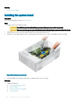
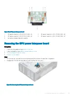
System board
Removing the system board
Prerequisites
CAUTION:
If you are using the Trusted Platform Module (TPM) with an encryption key, you may be prompted to create a
recovery key during program or System Setup. Be sure to create and safely store this recovery key. If you replace this system
board, you must supply the recovery key when you restart your system or program before you can access the encrypted data on
your hard drives.
CAUTION:
Do not attempt to remove the TPM plug-in module from the system board. Once the TPM plug-in module is installed,
it is cryptographically bound to that specific system board. Any attempt to remove an installed TPM plug-in module breaks the
cryptographic binding, and it cannot be reinstalled or installed on another system board.
1
Follow the safety guidelines listed in
2
Follow the procedure listed in
Before working inside your system
.
3
Remove the following:
a
b
, if installed
c
d
, if installed
e
, if installed
f
Integrated storage controller card
g
h
, if installed
i
Processors and heat sink modules
CAUTION:
To prevent damage to the processor pins when replacing a faulty system board, ensure that you
cover the processor socket with the processor protective cap.
j
Steps
1
Disconnect all cables from the system board.
CAUTION:
Take care not to damage the system identification button while removing the system board from the chassis.
CAUTION:
Do not lift the system board by holding a memory module, processor, or other components.
2
Holding the post, lift the blue release pin, and slide the system board toward the front of the system.
Sliding the system board toward the front of the chassis to disengage the connectors from the slots on the chassis.
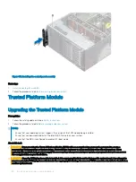
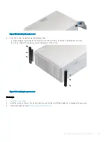
3
Holding the post, incline the system board at an angle, and lift the system board out of the chassis.
156
Installing and removing system components
Содержание PowerEdge T640
Страница 23: ...Figure 16 Configuration and layout Dell EMC PowerEdge T640 overview 23 ...
Страница 24: ...Figure 17 Electrical overview 24 Dell EMC PowerEdge T640 overview ...
Страница 25: ...Figure 18 Memory information Dell EMC PowerEdge T640 overview 25 ...
Страница 26: ...26 Dell EMC PowerEdge T640 overview ...


