DEGREE CONTROLS Rooster Sensor200 Скачать руководство пользователя страница 7

Rooster™ 

Sensor200 USER MANUAL 


Rooster™ 

Sensor200 USER MANUAL 62360MN000-A00


 7 of 40 

AIRFLOW RESOLUTION 

EH&S or Certifier users can select the resolution of air velocity units. 

Home>Settings>System>Airflow Settings>Airflow Resolution


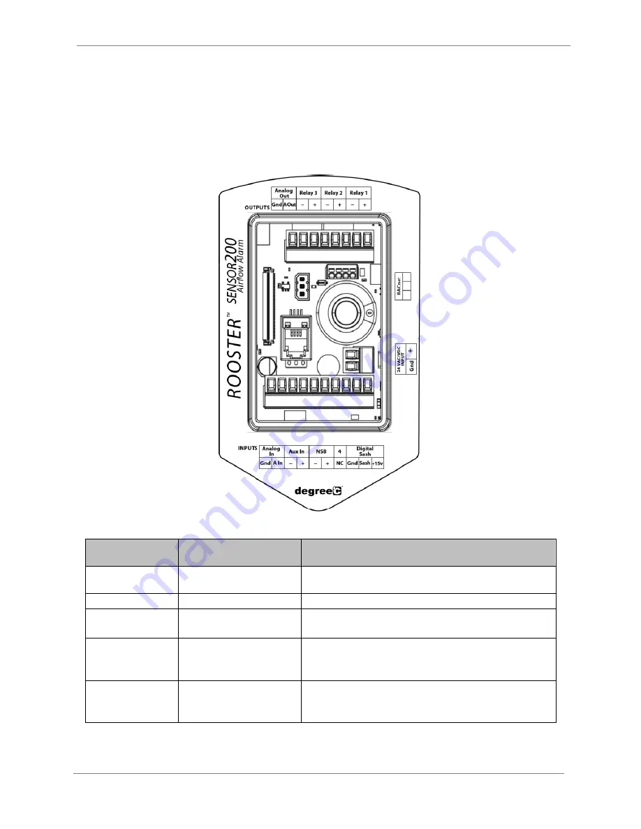
Rear Panel Layout for Advanced Connections 


Figure 1 Connections 

Connection 
Description 

Connector Type 

Mating Connector 

Power Entry 

2-Pin, polarized, Phoenix 
Contact 

Included and attached to AC/DC power supply 

Sensor Connection 

RJ-11 

Included as part of sensor assembly 

BACnet® Connection 

3-pin, push-in spring 
connection 

Not included 
3-position orderable Part Number: Phoenix Contact 1778845 

Output Connection 

8-pin, polarized, Phoenix 
Contact 
*2-position connectors will fit 

Not included 
8-position orderable Part Number: Phoenix Contact 1803633 
2-position orderable Part Number: Phoenix Contact 1803578 

Input Connection 

10-pin, polarized, Phoenix 
Contact 
*2-position connectors will fit 

Not included 
10-position orderable Part Number: Phoenix Contact 1803659 
2-position orderable Part Number: Phoenix Contact 1803578 

Table 1 Connections - Rear Panel of Display Module 

Содержание Rooster Sensor200

Страница 1: ...ocity and Temperature Sensor with Full Color Touch Screen Display BACnet MS TP Capable Version 1 06 Complete Kit includes o Sensor Display Panel o Sensor Probe and Mounting Clamp o Power Supply This is proprietary information of Degree Controls Inc contents are protected under US copyright laws Degree Controls Inc 2022 ...

Страница 2: ...TIFIER 17 Set Change Passwords 18 Calibration Sash Height 18 Sash Readings 18 Alarm Threshold Configuration 19 Alarm Troubleshooting 19 Alarm Controls 20 Night SetBack 20 Alarm Ringback 20 Alarm Delay 21 Startup Delay 21 Splash Screen 22 Latch Alarm 22 Alarm Tone Settings 22 Backlight Dimming 23 Airflow Settings 23 Airflow Sensitivity 23 Airflow Resolution 23 Volumetric Flow Settings 24 Air Change...

Страница 3: ...r as users may configure Sensor200 using its own touch screen display or remotely through BACnet The Rooster Sensor200 is feature rich delivering maximum flexibility and control to duct airflow monitoring applications Alarm output behavior is fully configurable and dual password protection allows users to personalize operational experience but not override safety features set by facility managers ...

Страница 4: ...er cases this LED will remain off Soft Buttons and Home Screen Layout Feature Overview CUSTOM ASSET TAG Users logged in as EH S can change default Asset Tag to a custom tag This is useful for naming the sensor in a larger distributed system or to denote a company asset number A 12 digit numeric asset tag can be set with the provided on screen keypad OR plug in a USB interface keyboard to enter a 1...

Страница 5: ... System Alarms Sound Device Volume ON SCREEN ALERT BANNERS A yellow banner will appear beneath on screen velocity readings to alert users regarding various scenarios such as low airflow or power failure Home TOGGLE VELOCITY UNIT TYPE Instantly toggle displayed velocity units from m s to fpm or vice versa by pressing on the displayed velocity reading on the home screen A third touch toggle of CFM i...

Страница 6: ... must be closed See the Alarm Threshold Configuration section for instructions on how to setup night setback alarm thresholds Home Settings System Alarms Sound Alarm Controls Night Setback ALARM LATCHING EH S or Certifier users can setup latched alarms to indicate that a low airflow state has occurred in the Alarm Controls menu User must then enter a EH S or Certifier passcode to unlatch an alarm ...

Страница 7: ...sor Connection RJ 11 Included as part of sensor assembly BACnet Connection 3 pin push in spring connection Not included 3 position orderable Part Number Phoenix Contact 1778845 Output Connection 8 pin polarized Phoenix Contact 2 position connectors will fit Not included 8 position orderable Part Number Phoenix Contact 1803633 2 position orderable Part Number Phoenix Contact 1803578 Input Connectio...

Страница 8: ...0 15 20 0 m s 30 4 000 fpm Response Time 1 second Supply Voltage 24VAC VDC Sash Switch Input Pin 1 15V Power For Proximity SW Pin 2 SASH Contact or Proximity Pin 3 GND Contact or Proximity Night Set Back Input Dry Contact Closure Pins 5 6 Auxiliary Input BACnet Monitored Dry Contact Closure Pins 7 8 Analog Input 0 10V Analog Pin 9 A IN Pin 10 GND Relay Outputs Qty 3 1A 24VAC DC Pins 1 2 Relay1 Pin...

Страница 9: ...d users can toggle between a digital or analog sash sensor input by navigating to Home Settings Sash Settings Digital Sash The default I O polarity of the digital sash position input is normally open The design intent is as follows The sash setting is set to Digital When the sash is in a safe position the proximity sensor should not detect a metallic object strip Sash position input logic may be r...

Страница 10: ...310AS008 uses pin 1 for 15V and analog input pins 9 and 10 on the input connector marked as Analog In Pin 1 15V Pin 9 A IN Pin 10 GND See the sash height calibration section for additional calibration detail See the I O configuration section to configure a relay output for Sash Alarm Note For implementation support or for users preferring to use a micro switch for sash alarm activation please cont...

Страница 11: ...200 alarm module Default I O polarity is normally open and output polarity logic may be changed via the Output Configuration menu of the Rooster Sensor200 The RoosterTM Sensor200 alarms for airflow and sash position and allows users to enable on screen buttons for accessory lamp and accessory fan Relay outputs are configurable and linked to alarms and accessory buttons from the output configuratio...

Страница 12: ...0 50 The primary purpose of the integral term is to eliminate the small steady state error between process flow and the setpoint It produces a correction based on the error over time The integral term can be any decimal value between 0 and 9999 and the default value for I term is 0 20 Scaled Output Scaled Output provides a control signal proportional to the face velocity or volumetric flow Scaled ...

Страница 13: ... the back plate Once this is complete the RoosterTM is easily aligned to the back plate and secured with bottom captive screw Two back plate versions are available 1 Wall Mount This back plate sits directly on the wall or cabinet surface and is secured by self tapping screws or industrial Velcro Sensor and control wiring access is at the back while access for power in from the wall mount power sup...

Страница 14: ...ush 3 Mark the surface where the RoosterTM alarm module will be located and make the necessary drills cutout 4 Secure back plate 5 Mount the sensor See below for sensor installation 6 Feed power and sensor wire harnesses through the opening s and make connections to the RoosterTM alarm module Make any other optional connections to the alarm module 7 Align top of alarm module with tabs on back plat...

Страница 15: ...tion 1 Mark the sensor hole and screw positions per Step 1 of C Clamp installation figure below 2 Drill a 17 32 14mm hole through the surface where you wish to install the sensor 3 Drill two pilot holes for the C Clamp fastening screws C Clamp Degree Controls P N 64500AS011 4 Secure the C Clamp with two screws not provided 5 Insert the sensor into the C Clamp and adjust the sensor s insertion dept...

Страница 16: ...e a power on switch and will become energized as soon as it is plugged in The RoosterTM boots to the screen depicted on the right with a slot for a custom logo The boot screen is designed to support a custom image or logo file in portable network graphic png format with 240x320 dimensions This feature must be requested and is not setup for manual configuration Once the start procedure has complete...

Страница 17: ... not require a passcode Access Privileges Defined Function Passcode Required Adjust Alarm Volume None Set Minimum Alarm Volume Threshold EH S Certifier Alarm Ringback Setting EH S Certifier Alarm Delay Setting EH S Certifier Startup Delay Setting EH S Certifier Alarm Latching Setting EH S Certifier Alarm Tones Settings EH S Certifier Mute Live Alarm None Perform Calibration Certifier Set Asset Tag...

Страница 18: ...ollows 1 Navigate to the Calibrate Sash Position screen by following this path Home Settings Calibrate Sash Position 2 Press the Calibrate button 3 In order to proceed you will need to enter your Certify password If you have not set a custom password the factory default is 6425 4 Move the sash to the fully closed position then select Continue to initiate the calibration Note The Sensor200 displays...

Страница 19: ...ip and clear based on your settings You may return to this menu at any time to adjust these values as needed 3 By default no values are set for the NSB Night Setback mode of operation Depending on your application or setup an active alarm during Night Setback may not be required Specific alarm trip and clear points for Night Setback mode may be entered First define an alarm trip point and an alarm...

Страница 20: ... Alarms Sound Alarm Controls Night Setback Note The definitions in the table below are with the I O Polarity of the NSB input set as normally open Night Setback Modes Definition Audible Enters Night Setback mode whenever relay is closed and audibly triggers an alarm when airflow drops below the NSB trip point To adjust Night Setback alarm thresholds navigate to Home Settings Thresholds Adjust Thre...

Страница 21: ...ount of time that the RoosterTM Sensor200 has to achieve continuous safe velocity readings before the alarm state clears and continuous unsafe velocity readings before an alarm is triggered This is called Alarm Delay Alarm Delay Definition 1s Alarm is cleared after 1 second if velocity readings are above the alarm clear threshold Alarm is triggered after 1 second if velocity readings are below the...

Страница 22: ...user has stepped away from the workstation When latching is On a yellow banner will display beneath the velocity and temperature readings on the home screen to indicate that a low airflow event has occurred When latching is set to Password an EH S passcode must be entered to unlatch this alarm If the Latch alarm setting is set to On tap the banner to disable the alarm Setting Alarm Latch to Off di...

Страница 23: ...west dimness setting will not allow the screen to turn completely dark instead it will be just bright enough to still be readable Dim times are 1 5 10 and 60 minutes with an Off setting and a default time of 10 minutes initially Home Settings System Brightness Airflow Settings Airflow Sensitivity This setting smooths airflow readings by applying a filter that determines sensitivity of readings Hom...

Страница 24: ... duct information The steps are as follows 1 Navigate to the System screen by following this path Home Settings System 2 Push the Airflow Settings button to enter the Airflow Settings menu screen Home Settings System Airflow Settings 3 In order to proceed you will need to enter your Certify password If you have not set a custom password the factory default is 6425 4 Push the Volumetric Flow Settin...

Страница 25: ... the rear panel of the alarm module Prior to a BACnet device discovery the MAC Address and MAC ID of the RoosterTM must be set at the alarm module and the RoosterTM power cycled for 5 seconds A BACnet Settings menu screen is provided to change the MAC Address and MAC ID for network configuration Home Settings BACnet Settings Familiarize yourself with all functions and behaviors invoked by RoosterT...

Страница 26: ...ER MANUAL Rooster Sensor200 USER MANUAL 62360MN000 A00 26 of 40 BACnet MS TP Objects The RoosterTM BACnet MS TP interface allows users to extensively configure and monitor the device See the objects table below for details ...

Страница 27: ... Low Alarm Clear Analog Value 4 m s 0 to 40 99 R W Low air velocity value that will clear an alarm 85 High Alarm Trip Analog Value 5 m s 0 to 40 99 R W High air velocity value that will trigger an alarm No value set High Alarm Clear Analog Value 6 m s 0 to 40 99 R W High air velocity value that will clear an alarm No value set NSB Low Alarm Trip Analog Value 7 m s 0 to 40 99 R W Low air velocity v...

Страница 28: ...width 0 Valid if the selected duct area is rectangle Duct Dia Analog Value 15 cm 0 to 183 R W Airflow duct area diameter 0 Valid if the selected duct area is circle Face Velocity Analog Input 0 m s 0 to 5 R Real time face velocity with sash in any position No value set Air Temperature Analog Input 1 C 0 150 R Air temperature F Airflow Changes Per Hour Analog Input 2 NA R Number of times the air in...

Страница 29: ...calibration Normal Setting Allowed Turbulence to High will help you overcome cabinet level airflow instability issues It should be reserved for rare circumstances where there is difficulty achieving stable laminar airflow Sash Calibration Status Binary Input 4 0 Uncalibrated 1 Calibrated 0 1 R Sash calibration status Uncalibrated Sash calibration is associated with Sash Type analog Relay1 Status B...

Страница 30: ...1 R W Enable or disable the display of volumetric flow on the RoosterTM Disabled A non zero value for volumetric flow can be displayed on the RoosterTM provided duct information is entered Duct Shape Binary Value 5 0 Circle 1 Rectangle 0 1 R W Shape of airflow duct Circle Sash Digital Input Polarity Multi State Value 0 1 Normally Open 2 Normally Closed 3 Disabled 1 2 3 R W Sash digital input polar...

Страница 31: ...tatus when not active Normally Open Relay3 Polarity Multi State Value 7 1 Normally Open 2 Normally Closed 3 Disabled 1 2 3 R W Relay out polarity status when not active Normally Open Relay1 Functionality Multi State Value 8 1 Sash Alarm 2 Flow Alarm 3 Light 4 Fan 5 Null 1 2 3 4 5 R W Relay functionality Flow Alarm Relay2 Functionality Multi State Value 9 1 Sash Alarm 2 Flow Alarm 3 Light 4 Fan 5 N...

Страница 32: ...5 5 min 1 2 3 4 5 R W Amount of time alarm is paused on startup 30 sec Probe Type Multi State Value 15 1 Probe 2 Sidewall 3 Inline 1 2 3 R W Sensor type to be calibrated Sidewall Alarm Delay Multi State Value 16 1 1 sec 2 2 sec 3 5 sec 4 10 sec 1 2 3 4 R W Amount of time that the RoosterTM has to achieve continuous safe velocity readings before the alarm state clears and continuous unsafe velocity...

Страница 33: ...Character String Value 2 Standard serial number format R Serial number of RoosterTM RoosterTM information ID Data Rooster Caldate Character String Value 3 Standard date format R Calibration date NA RoosterTM information airflow sensor calibration date Sash Caldate Character String Value 4 Standard date format R Sash calibration date NA RoosterTM information Analog Sash calibration date ...

Страница 34: ...p on or off Fan is a separate on screen accessory button which can be used to turn a fan on or off Once the user links an accessory button to a relay output from the grid the button is enabled and displayed on the main screen of the Sensor200 Accessory buttons reflect the on off status of the connected devices Press the button to toggle the connected device on or off Links to Relay Outputs Relay o...

Страница 35: ...ve for future use Importing the EEPROM configuration file to other RoosterTM Sensor200s in your facility ensures operational consistency and saves valuable setup time Plug a USB thumb drive into the RoosterTM and navigate to the Import Export menu to select the Import EEPROM or Export EEPROM function Home Settings System Advanced Import Export Event Log The RoosterTM logs the date and time of alar...

Страница 36: ... Thus the update should only be done during annual certification where the user would have the Rooster recalibrated anyway OR if the client approves forcing a recalibration The first step of the firmware upgrade process is to identify the current version of Rooster firmware Next use the table below to evaluate the effects of an upgrade and determine the best time to update your Rooster Upgrade Fro...

Страница 37: ...he firmware release information listed next to firmware should have changed to the most current build If this is not the case repeat the upgrade procedure Power Cycle Procedure Procedure 1 Remove power from the RoosterTM 2 Insert USB thumb drive into left side of the RoosterTM 3 Depress and hold the Home button while reapplying power to your unit Hard Home button must be depressed while RoosterTM ...

Страница 38: ... USER MANUAL 62360MN000 A00 38 of 40 2 The Enter Certify Password screen will display The factory default Certifier password is 6425 This can be changed by accessing the Advanced menu 3 The Factory Menu will display Depress Reset to Factory Defaults ...

Страница 39: ...Rooster Sensor200 USER MANUAL Rooster Sensor200 USER MANUAL 62360MN000 A00 39 of 40 GUI Map ...

Страница 40: ...ured by DegreeC Such parts components or products may be warranted by third parties on a pass through basis The foregoing remedies shall not apply to any product failure caused in whole or in part by i Buyer s failure to operate maintain or service the products in accordance with DegreeC s documentation ii any alteration modification or repair made to the products other than by DegreeC or iii use ...

Отзывы: