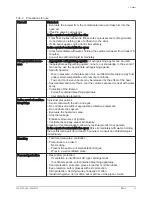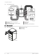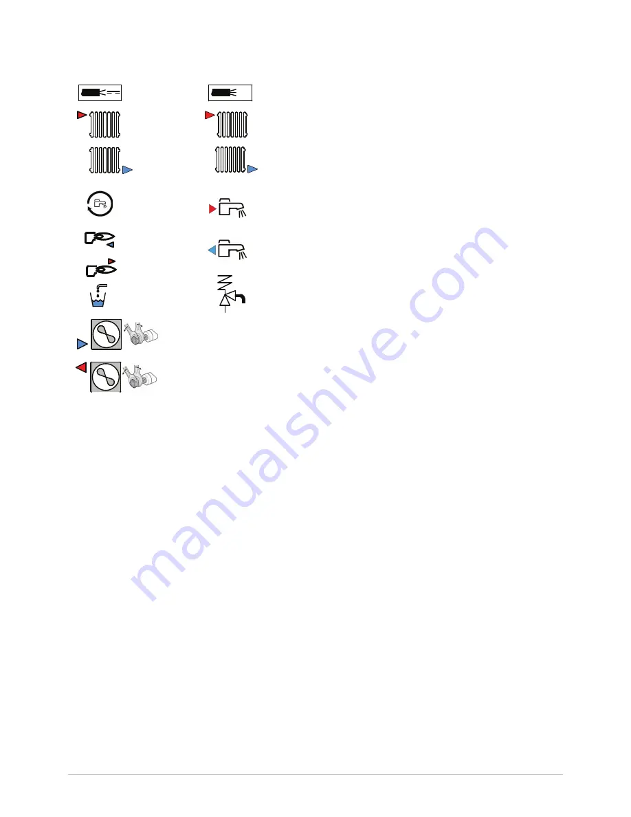
1 Sensor cable - low voltage
2 Power cord 230 V
3 Heating circuit flow
4 Circuit B flow
5 Heating circuit return
6 Circuit B return (optional)
7 Connection for recirculation
8 Domestic hot water outlet
9 Flow to boiler back-up (only for versions with hydraulic back-up)
10 Return from boiler back-up (only for versions with hydraulic back-
up)
11 Domestic cold water inlet
12 Drain valve
13 Safety valve
14
3
/
8
" refrigerant fluid connection - liquid line
15
5
/
8
" refrigerant fluid connection - gas line
Fig.3
Symbols used on the connection la
bel
G3/4"
A
G1"
A
G1"
B
G1"
B
G1"
G3/4"
G3/4"
5/8
69-82 Nm
3/8
34-42 Nm
Ø13
1
2
4
6
8
10
12
3
5
7
9
11
13
MW-6000285-1
14
15
2 About this manual
7623755 - v02 - 03072015
MIV-4
15

