background image

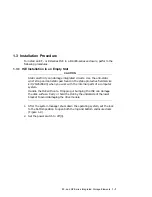
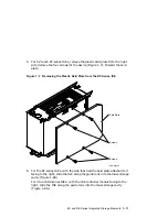
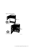
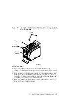
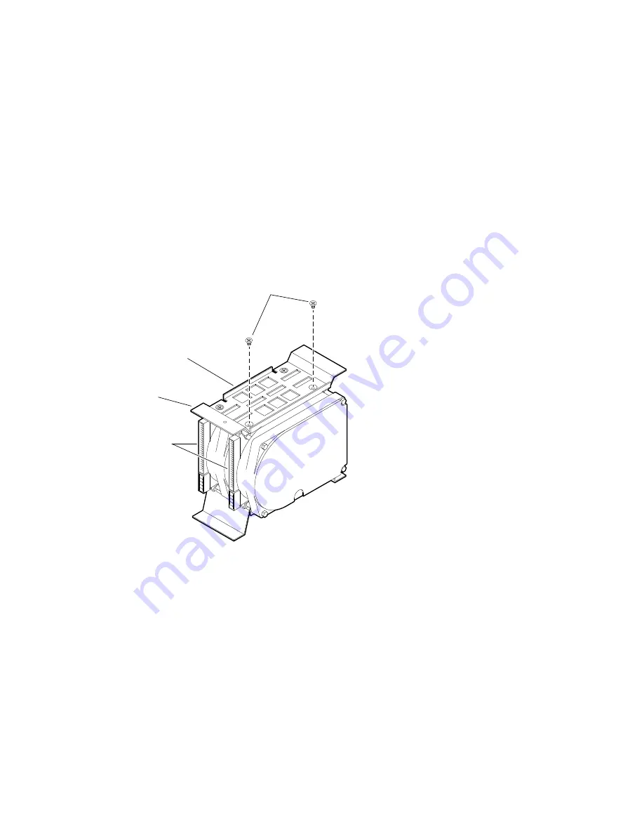
Figure 1–12 Installing the Phillips Screws That Secure the Storage Device to

the Inside Brackets

Phillips

Screws

Bottom Inside
Bracket

Bottom of ISE

Controller
Modules

MLO-007246

Installation Notes

When you install the new drive, be sure to complete the following:

1.

Align the new storage device in the same orientation as the original device.

2.

When reinstalling the top outside bracket, lift the bracket’s rear slot over
the flange of the plastic interface card assembly, and then over the tab at
the back of the bottom outside bracket. Both the tab and the flange must
be inside the rear slot of the top outside bracket.

3.

Make sure that the grounding foil is in place under the front mounting
screw on the bottom outside bracket.

EF- and RZ-Series Integrated Storage Elements 1–21

Содержание BA400 Series

Страница 1: ...400 Series Enclosures Storage Devices Installation Procedures Order Number EK BA44A IN K01 Revision Information This manual supersedes EK BA44A IN J01 Digital Equipment Corporation Maynard Massachuset...

Страница 2: ...tion CompacTape CX DDCMP DEC DECconnect DECdirect DECnet DECscan DECserver DECUS DECwindows DELNI DEMPR DESQA DESTA DSRVB DSSI IVAX KDA KLESI KRQ50 MicroVAX MSCP Q bus Q22 bus RA RQDX RV20 SA SDI Thin...

Страница 3: ...1 20 1 4 3 Installing Upgraded ISEs in the Mass Storage Cavity 1 22 1 4 4 Bus Node ID Configuration Guidelines 1 23 1 5 Power On Self Test POST 1 24 1 5 1 EF Series POST 1 24 1 5 2 RZ Series POST 1 2...

Страница 4: ...lation 3 11 3 4 1 RRD CD ROM Power On Self Test 3 11 3 5 Setting the ISE Parameters 3 11 4 RRD TLZ07 Dual ISE Drives 4 1 General 4 1 4 2 RRD TLZ07 DUAL ISE Installation Preparation 4 1 4 3 Installatio...

Страница 5: ...lips Screws That Secure the Storage Device to the Inside Brackets 1 21 1 13 Installing the ISE Upgrade in the Storage Cavity 1 23 2 1 Opening the Enclosure Doors 2 4 2 2 Installing the TLZ07 Drive 2 6...

Страница 6: ...Tables 1 1 DVTST Error Messages 1 33 5 1 Power on Self test Events 5 8 vi...

Страница 7: ...orage elements Chapter 2 describes the installation of TLZ series tape drives Chapter 3 describes the installation of RRD series CD ROM drives Chapter 4 describes the installation of RRD TLZ07 dual IS...

Страница 8: ......

Страница 9: ...side for the RZ series The two configurations vary as follows EF series ISEs are solid state disks 3 5 inch RZ series ISEs contain either one or two hard disk storage devices BA400 series ISEs contai...

Страница 10: ...Figure 1 1 EF Series ISE Front and Rear View MLO 009301 Front View Rear View Bracket Slides Bracket Slides 1 2 EF and RZ Series Integrated Storage Elements...

Страница 11: ...2 3 5 inch RZ Series ISE Rear View 4 Pin Power Cable 50 Pin Signal Cable From back of drive the screw hole is offset to the right for SCSI RZ Series MLO 011782 EF and RZ Series Integrated Storage Elem...

Страница 12: ...can be embedded within a CPU module such as the KA670 module The DSSI interface can also be separate modules such as the KFQSA which is interfaced by a single cable to a DSSI connector in the host en...

Страница 13: ...sure There can be three 3 5 inch dual storage devices and one 5 25 inch or one 3 5 inch single storage device For more detailed information about configuring EF and RZ series ISEs in a BA400 series en...

Страница 14: ...ill cause improper operation of the ISE Note Some of the ISEs have two sets of jumpers for setting the bus node ID Refer to the reference booklet or data sheet that is shipped with the ISE to set the...

Страница 15: ...field service kit 29 26246 00 when you work with the internal parts of a computer system Handle the ISE with care Dropping or bumping the ISE can damage the disk surface Carry or hold the ISE by the...

Страница 16: ...Figure 1 4 Power Switch Location Power Switch MLO 006627 1 8 EF and RZ Series Integrated Storage Elements...

Страница 17: ...Slot 0 NOTE The first slot 0 mass storage cavity in the mass storage area is wider than the rest to accommodate a larger device such as a tape drive A small filler panel 70 27414 01 is used to fill t...

Страница 18: ...ptive Phillips screw that secures the blank ISE front panel assembly Figure 1 6 and remove the panel Figure 1 6 Blank Front Panel Assembly Phillips Screw MLO 007236 1 10 EF and RZ Series Integrated St...

Страница 19: ...MLO 009302 Skid Plate Screws Screws 6 For the EF series ISEs with the side that had the skid plate attached to it facing to the right slide the ISE along the guide rails into the mass storage cavity...

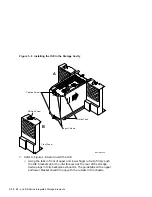
Страница 20: ...e 1 8A and install the ISE p Using the tabs in front of upper and lower finger cutouts firmly push the ISE brackets until the interface card at the rear of the storage device plugs into its backplane...

Страница 21: ...en the captive screws only until they are securely fastened 9 inch pounds Do not try to force the tabs to fit flush against the frame 9 Attach the ISE front panel to the enclosure by first fitting the...

Страница 22: ...can damage integrated circuits Always use the antistatic wrist strap and antistatic pad found in the static protective field service kit 29 26246 00 when working with the internal parts of a computer...

Страница 23: ...Figure 1 9 Keylock Positions MLO 004034 Top Key Position MLO 004035 Bottom Key Position MLO 012859 Key Lock Power Switch EF and RZ Series Integrated Storage Elements 1 15...

Страница 24: ...ackets carefully pull the ISE out of its backplane connector and slide the drive out of the enclosure Support the weight of the ISE at the underside of the lower bracket as the ISE clears the enclosur...

Страница 25: ...ure 1 10 Removing the ISE to Be Upgraded or Replaced Phillips Screw Front Panel Captive Screws Finger Cutouts Guide Tabs MLO 007247A 1 2 3 4 pull loosen EF and RZ Series Integrated Storage Elements 1...

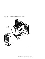
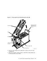
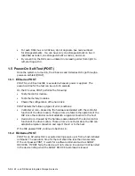
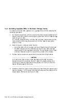
Страница 26: ...move the Top Outside Bracket Complete the following steps to remove the top outside bracket from the ISE Note Note the orientation of the mounting bracket before you take it apart refer to Figure 1 2...

Страница 27: ...s offset to the right for SCSI MLO 011783 Top Bracket Tab Flange Interface Card Assembly 4 Gently turn the storage device upside down so that it rests on the top inside bracket 5 After removing both m...

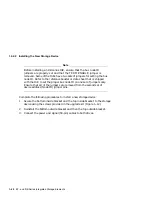
Страница 28: ...roper bus node ID on one set of jumpers only Ensure that all of the jumpers are removed from the second set of device address Node ID jumper pins Complete the following procedures to install a new sto...

Страница 29: ...evice in the same orientation as the original device 2 When reinstalling the top outside bracket lift the bracket s rear slot over the flange of the plastic interface card assembly and then over the t...

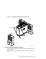
Страница 30: ...s firmly push the ISE brackets until the interface card at the rear of the storage device plugs into its backplane connector The guide tabs on the upper and lower bracket should line up with the cutou...

Страница 31: ...ws Finger Cutouts Guide Tabs MLO 007244A 1 4 4 Bus Node ID Configuration Guidelines The EF and RZ series ISEs require setting jumpers on the storage device for the bus node ID Use the following rules...

Страница 32: ...rror conditions Controller errors Caused by the hardware associated with the controller function of the drive module These errors are fatal to the operation of the ISE since the controller cannot esta...

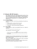
Страница 33: ...command Through MDM using the Device Resident Programs menu 1 6 1 1 Using OpenVMS To access PARAMS on a system running OpenVMS Version 5 3 or higher the command is SET HOST DUP SERVER MSCP DUP TASK P...

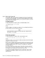
Страница 34: ...system with a Q bus adapter enter SET HOST DUP UQSSP DISK controller_number PARAMS where controller_number is the controller number provided by the SHOW UQSSP display for the device on the bus After...

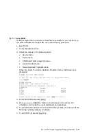
Страница 35: ...halt the test at any time and return to the previous menu type CTRL C KFQSAA started KFQSAA pass 1 test number 3 started Copyright 1988 Digital Equipment Corporation Completed EXIT DRVEXR DRVTST HIST...

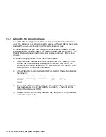
Страница 36: ...the allocation class 1 Determine what the allocation class should be set to by reading it from another ISE that is already working on the system Use one of the procedures outlined in Section 1 6 1 to...

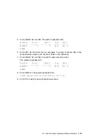
Страница 37: ...allocation class as all the other ISEs on the DSSI bus 7 Enter SHOW ALLCLASS to check the new allocation class The system responds with Parameter Current Default Type Radix ALLCLASS 1 0 Byte Dec B PAR...

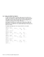
Страница 38: ...meter to 0 This allows the unit number you have set to be used The factory setting for FORCEUNI is 1 forcing the DSSI node ID to be used as the MSCP unit number The following example shows how to chan...

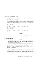
Страница 39: ...B PARAMS write NOTE Using the WRITE command will make any changes permanent 1 7 Testing the ISE CAUTION Running DRVTST may erase all user data on the ISE and should only be used when installing a new...

Страница 40: ...read write test and DRVTST prompts you with another query In this case type 1 Return selecting a read write test DRVTST then displays the following User data will be corrupted Proceed 1 Yes 0 No This...

Страница 41: ...or that the read write head was temporarily off track These are corrected during normal operation xxxx Unit diagnostics failed This is a fatal error xxxx is the MSCP error code xxxx Unit read write te...

Страница 42: ......

Страница 43: ...System Interface SCSI The following table lists the storage capacity for each type of 4 mm data cassette Tape Type With No Compression With Compression TLZ04 CA 60 m 1 1 3 GB 2 6 GB TLZ06 CA 90 m 2 2...

Страница 44: ...rs are removed and that the TERM PWR and the TERM ENABLE DIP switches are set to 0 Failure to remove the TERM ENABLE jumper or set the TERM ENABLE DIP switch to 0 termination disabled will cause impro...

Страница 45: ...grated circuits Use the antistatic wrist strap and antistatic pad found in the static protective field service kit 29 26246 00 when you work with the internal parts of a computer system 1 Open the top...

Страница 46: ...Figure 2 1 Opening the Enclosure Doors MLO 004034 Top Key Position MLO 004035 Bottom Key Position MLO 012856 Key Lock Slot 0 Power Switch 2 4 TLZ Series Tape Drives...

Страница 47: ...the drive installation a Tighten the captive screws at the top and bottom of the bracket 1 CAUTION It is normal for there to be a small gap between the mounting bracket tabs and the enclosure frame Ti...

Страница 48: ...Figure 2 2 Installing the TLZ07 Drive 1 Tighten screw 2 Insert bezel 3 Tighten screw MLO 011787 2 6 TLZ Series Tape Drives...

Страница 49: ...e cassette is loaded the Casette indicator remains on After completing a successful execution of the POST have the system manager restart the operating system and assign a device name to the TLZ07 dri...

Страница 50: ......

Страница 51: ...drives require that bus node ID jumpers be set on the drive before the ISE is installed in a BA400 series enclosure When installing an RRD series CD ROM drive refer to the reference booklet or data sh...

Страница 52: ...26246 00 when you work with the internal parts of a computer system 1 Open the top and bottom enclosure doors 2 Power off the system and unplug the power cord from the wall outlet 3 Loosen the captiv...

Страница 53: ...Figure 3 1 Opening the Enclosure Doors MLO 004034 Top Key Position MLO 004035 Bottom Key Position MLO 012857 Key Lock Slot 3 Slot 2 Slot 1 Power Switch RRD Series CD ROM Drive 3 3...

Страница 54: ...gap between the mounting bracket guide tabs and the enclosure frame Tighten the captive screw only until it is securely fastened 9 inch pounds Do not try to force the tabs to fit flush against the fr...

Страница 55: ...Figure 3 2 Inserting the RRD CD ROM drive Phillips Screw B Captive Screw A Finger Cutouts Guide Tabs MLO 011784 RRD Series CD ROM Drive 3 5...

Страница 56: ...8 Locate the KZQSA IN connector on the I O bulkhead Figure 3 3 KZQSA IN Connector MLO 007150 KZQSA In 3 6 RRD Series CD ROM Drive...

Страница 57: ...the KZQSA IN connector Figure 3 4 Removing the Connector Cover Protective Cover MLO 007168 10 Locate the KZQSA internal cable labeled BC06P 2F that ships with the RRD drive Figure 3 5 KZQSA Cable MLO...

Страница 58: ...connector p Press the bail latches onto the cable connector to lock it in place Figure 3 6 Connecting to KZQSA IN MLO 007152 12 Locate the KZQSA module identified by the KZQSA SA indentification label...

Страница 59: ...Figure 3 7 KZQSA Label KZQSA SA M5976 SA MLO 007153 13 Remove the terminator from the upper connector on the module Figure 3 8 KZQSA Module Connector MLO 007179 RRD Series CD ROM Drive 3 9...

Страница 60: ...e KZQSA module connector p Press the bail latches onto the cable connector to lock it in place Figure 3 9 Connecting to KZQSA IN KZQSA Bail Latch Feed Cable Under System and Up Through Opening S A M59...

Страница 61: ...continuously then the POST failed p Attempt to clear the failure by powering off the system and then re executing the POST p Check to be sure the CD is not loaded upside down p Check and reseat all IS...

Страница 62: ......

Страница 63: ...sure that the TERM PWR and the TERM ENABLE jumpers are removed Failure to remove the TERM ENABLE jumper will cause improper operation of the drive TLZ07 tape drives require that bus node ID jumpers or...

Страница 64: ...n Procedure Use the following procedure to install the dual ISE drives into a BA400 series enclosure Have the system manager shut down the operating system before installing the ISE CAUTION Static ele...

Страница 65: ...Figure 4 1 Opening the Enclosure Doors MLO 004034 Top Key Position MLO 004035 Bottom Key Position MLO 012856 Key Lock Slot 0 Power Switch RRD TLZ07 Dual ISE Drives 4 3...

Страница 66: ...s into its backplane connector 6 Refer to Figure 4 2 to complete the installation of the drives a Tighten the captive screws at the top and bottom of the bracket 1 CAUTION It is normal for there to be...

Страница 67: ...Figure 4 2 Installing the RRD TLZ07 Dual ISE 1 Tighten screw 2 Insert bezel 3 Tighten screw MLO 011786 RRD TLZ07 Dual ISE Drives 4 5...

Страница 68: ...mately 10 to 20 seconds Successful POST After successful completion of the POST the Busy indicator shuts off Have the system manager restart the operating system and assign a device name to the CD ROM...

Страница 69: ...have the system manager restart the operating system and assign a device name to the TLZ07 drive Unsuccessful POST The POST failed if the Cassette and Write Protect indicators flash continuously for m...

Страница 70: ......

Страница 71: ...n lo a d T Z 8 6 W a it L ig h t O p e n t h is H a n d le I n s e r t T a p e C lo s e t h is H a n d le P r e s s B u t t o n W a it L ig h t O p e n t h is H a n d le R e m o v e T a p e Cartridge...

Страница 72: ...TZ series tape drives require that bus node ID jumpers or DIP switches be set on the drive before the ISE is installed in a BA400 series enclosure The TZ series tape drive has both jumpers and DIP swi...

Страница 73: ...HSD10 option is installed CAUTION Static electricity can damage integrated circuits Use the antistatic wrist strap and antistatic pad found in the static protective field service kit 29 26246 00 when...

Страница 74: ...rage slot 0 Note The TZ series tape drive is installed only in mass storage slot 0 3 With the tape drive right side up Unload button at top slide the drive Figure 5 3A into mass storage slot 0 4 Using...

Страница 75: ...unting bracket tabs and the enclosure frame Tighten the captive screws only until they are securely fastened 9 inch pounds Do not try to force the tabs to fit flush against the frame b Attach the ISE...

Страница 76: ...Figure 5 3 Installing the TZ Series Drive Phillips Screw B Captive Screws 2 A Finger Cutouts Guide Tabs MLO 011788 5 6 TZ Series Tape Drive...

Страница 77: ...Figure 5 4 shows the TZ series tape drive installed in the enclosure Figure 5 4 TZ Series Drive Installed in Mass Storage Slot 0 MLO 006528 Slot 3 Slot 2 Slot 1 Slot 0 TZ Series Tape Drive 5 7...

Страница 78: ...ape in Use indicator flashes while the tape drive initializes 5 After initialization with no cartridge loaded the green Operate Handle indicator lights and a beep sounds 1The Write Protected indicator...

Страница 79: ...same manner as the RZ series ISEs Refer to the HSD05 DSSI to SCSI Bus Adapter Operation Information for BA400 Based VAX 4000 Systems manual EK HSDC5 IN or the HSD10 DSSI to SCSI Bus Adapter Operation...

Страница 80: ......

Страница 81: ...ies Cartridge Tape Subsystems EK OTX86 OM TZ87 Cartridge Tape Subsystems EK OTZ87 OM TZ88 DLT Series Tape Drive Owner s Manual EK TZ88N OM BA400 Series Mass Storage Devices EK 441AC IP HSD05 DSSI to S...

Страница 82: ......

Страница 83: ...element 1 1 1 4 installation preparation 1 6 installation procedure 1 7 F Front panel assembly 1 4 H Hierarchical storage controllers HSCs 1 28 I Installing new ISEs in the mass storage cavity 1 22 I...

Страница 84: ...RRD Series CD ROM Drive general description 3 1 RRD TLZ07 Dual ISE general description 4 1 installation preparation 4 1 RZ series integrated storage element 1 1 1 4 installation preparation 1 6 instal...

Страница 85: ...Digital Equipment Corporation P O Box CS2008 Nashua NH 03061 Puerto Rico Phone 809 781 0505 Fax 809 749 8377 Digital Equipment Caribbean Inc 3 Digital Plaza 1st Street Suite 200 Metro Office Park San...

Страница 86: ......
Страница 87: ...Clarity easy to understand Organization structure of subject matter Figures useful Examples useful Index ability to find topic Page layout easy to find information I would like to see more less What I...

Страница 88: ...CLASS PERMIT NO 33 MAYNARD MASS POSTAGE WILL BE PAID BY ADDRESSEE No Postage Necessary If Mailed in the United States DIGITAL EQUIPMENT CORPORATION Shared Engineering Services DIGITAL DRIVE MKO1 2 E1...

Отзывы: