background image

44

DriveRack

®

DriveRack® 260 User Manual

Utilities/Meters

Section 5

•  Once the list size has been selected, press the 

DATA

 wheel. Rotate the 

DATA

 wheel to select Index 1, if it is 

not already selected. Press the 

DATA

 wheel in again to move down to the program selection parameter. Rotate 

the 

DATA

 wheel to select the program which you would like to appear first in your custom program list. Press 

the 

DATA

 wheel twice to move back to the List Index parameter and rotate the 

DATA

 wheel to set this to 

List Index number 2. Press the 

DATA

 wheel again, then rotate the 

DATA

 wheel to select which program you 

would like to appear second in your custom program list. Repeat this process for all programs which you want to 
appear in your custom program list. 

•  Once you are done creating your custom Program List you need to turn Program List Mode on. To do this press 

the 

NEXT PG

 button. The display will appear something like this:

Utility

LCD Contrast 

10

Auto EQ Plot 

RTA

Power Up Modes

PUP Program    Stored

PUP Mute 

   Current

ZC Setup

 Panel 1      None

(STORE) - EDIT PANEL

Panel 1 

   ZC-2

Boost  0dB  Cut   0dB

Output

1     3     5 
2     4     6 

Set Security Level

 Pre EQ

 Low

Set 260 Device Level

 High


Password

 Enter Password 

Password

 Edit High Password

 Edit Med Password 

Press Store to Change

Press Store 

Program List

 List Size        10

 List Index        1

  Program 1

Prog Change Mode

 Program List     

Prog Lock         24  

Output Jumpers

Output             1     

Setting           30  

Panel 1 

   ZC-3

Select A

No Change

Panel 1 

   ZC-4

  Switch

  No Change

1 2 3 4

<DATA> - SELECT CHARACTER
<PREV/NEXTPG> - LEFT/RIGHT:
<STORE>-SAVE/<UTIL>-EXIT

 NAME:  

R

OCK VENUE

<DATA> - SELECT CHARACTER
<PREV/NEXTPG> - LEFT/RIGHT:
<STORE>-SAVE/<UTIL>-EXIT

 NAME:  

•  Turn the 

DATA

 wheel to change the Program Change Mode from ‘Normal’ to ‘Program List’. 

•   Once your program list has been built and Program Change Mode turned on, press the 

PROGRAM/CONFIG


button to exit.  

•  Now as you turn the 

DATA

 wheel, you should see only the programs which you assigned in your custom 

program list. If at any time you would like to set the Program List Mode back to normal, simply press the 

UTILITY

 button, go back to the ‘Prog Change Mode’ page and switch the mode from ‘Program List’ to ‘Normal’.

Note:

 The Program Lock parameter shown in the above screen shot allows you to prevent overwriting of certain User 

Programs. All program numbers from the set number and below will be locked and cannot be overwritten.
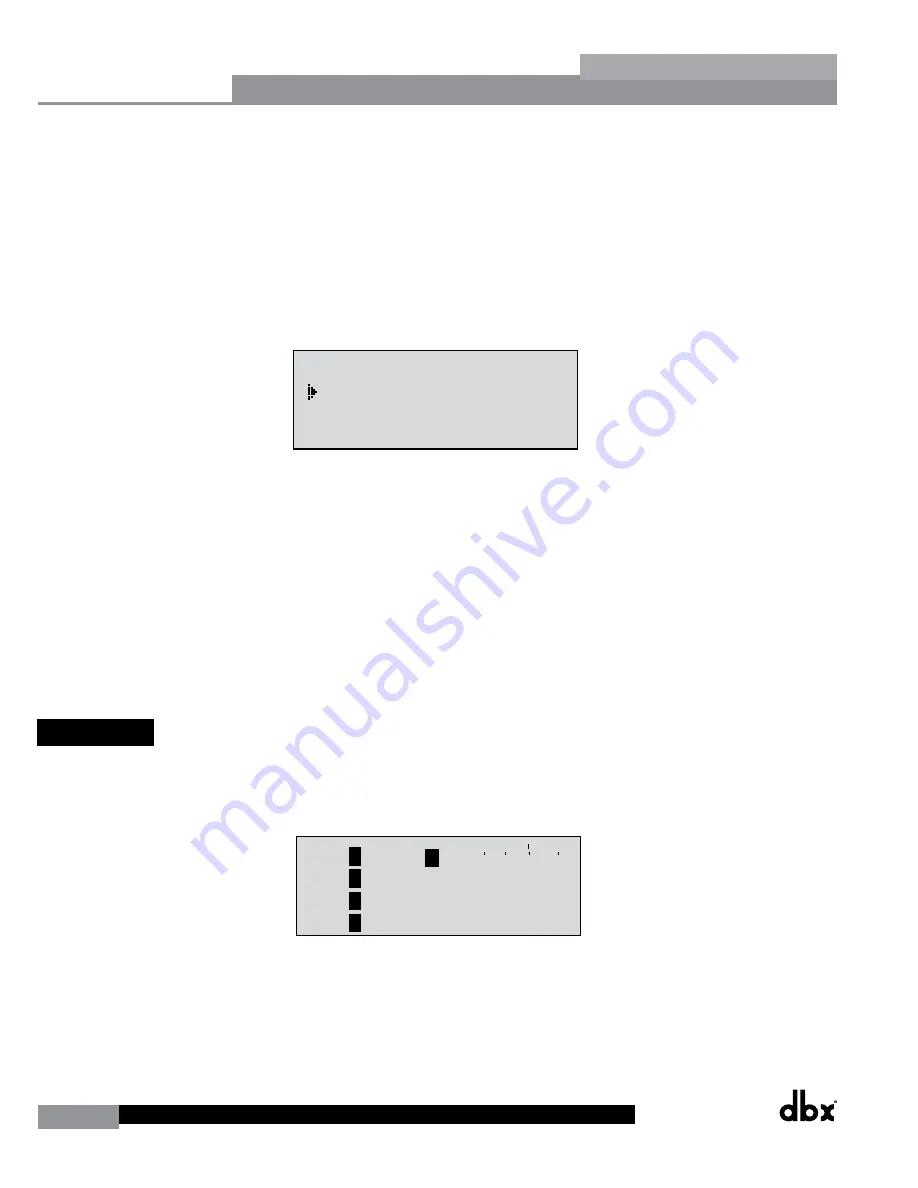
 5.6 Meters 

To meter various aspects of the 260, press and hold the 

UTILITY

 button until the display enters the Metering section.

•  Use the 

PREV PG

 or

 NEXT PG 

button to move to the page that appears as follows:

INS  COMP  o+

 1

INS

 2

-30-20 0 +20

-

A

B

A

B

LIM

0+

LIM

LIM

-30-20 0 +20

-

0+

-

0+

-

1

2

3

LIM

0+

LIM

LIM

-30-20 0 +20

-

0+

-

0+

-

4

5

6

Trim  0.0 Net   0.0 dB

Trim  0.0 Net   0.0 dB

Trim  0.0 Net   0.0 dB

1

2

3

Zone Controllers

Panel 1

Panel 2

Panel 3

Zone Controllers

Panel 4

Panel 5

Panel 6

Output Trims

Trim  0.0 Net   0.0 dB

Trim  0.0 Net   0.0 dB

Trim  0.0 Net   0.0 dB

4

5

6

Output Trims

 This page meters the gain reduction of any Dynamic block configured in the Insert 1 or Insert 2 block.

•  Use the 

PREV PG

 or

 NEXT PG

 button to move to the page that appears as follows:

Содержание DriveRack 260

Страница 1: ...User Manual DriveRack CompleteEqualization LoudspeakerManagementSystem Featuring Custom Tunings 260...

Страница 2: ...ges 26 Section 4 Detailed Parameters 4 1 Pre Crossover EQ 28 Band GEQ or 9 Band PEQ 27 4 2 Feedback Eliminator 28 4 3 Subharmonic Synthesizer 29 4 4 Gate 30 4 5 Automatic Gain Control AGC 31 4 6 Notch...

Страница 3: ...ent components the configuration possibilities are limitless After you have become familiar with the unit we encourage you to experiment and find the most effective and efficient way to run your syste...

Страница 4: ...cal support contact dbx Technical Support Be prepared to accurately describe the problem Know the serial number of your device this is printed on a sticker attached to the chassis Before you return a...

Страница 5: ...to dbx WITH RETURN AUTHORIZATION from the factory where all parts and labor will be covered up to a period of two years A Return Authorization Number must first be obtained from dbx The company shall...

Страница 6: ...ack 260 PC Connection This DB 9 type connection is used to send and receive information to and from the GUI interface and for firmware updates RS485 Zone Control Input RJ 45 connector type This input...

Страница 7: ...d navigating functions of the DriveRack 260 See sections 2 1 Basic Navigation Modes and 2 2 Effect Button Array Overview for a detailed description on the functions of each of these buttons Input Mete...

Страница 8: ...2 all frequencies are passed 2 Way Outputs 1 2 highs Outputs 3 4 lows 3 Way Outputs 1 2 highs Outputs 3 4 midrange Outputs 5 6 lows Of course you do have options to configure the DriveRack 260 differe...

Страница 9: ...DriveRack DriveRack 260 User Manual 7 Getting Started Section 1 Step by step Setup Procedure...

Страница 10: ...8 DriveRack DriveRack 260 User Manual Getting Started Section 1...

Страница 11: ...DriveRack DriveRack 260 User Manual 9 Getting Started Section 1...

Страница 12: ...10 DriveRack DriveRack 260 User Manual Getting Started Section 1...

Страница 13: ...DriveRack DriveRack 260 User Manual 11 Getting Started Section 1...

Страница 14: ...12 DriveRack DriveRack 260 User Manual Getting Started Section 1...

Страница 15: ...DriveRack DriveRack 260 User Manual 13 Getting Started Section 1...

Страница 16: ...14 DriveRack DriveRack 260 User Manual Getting Started Section 1...

Страница 17: ...NAMICS Selects the Dynamics effect sections Successive presses of this button will toggle through the pre crossover dynamics modules Compressor Gate or AGC and post crossover dynamics modules AGCs or...

Страница 18: ...20 to 16 0 B2 Freq 20Hz 20kHz Gain 12dB to12dB Q 20 to 16 0 B2 Freq 20Hz 20kHz Gain 12dB to12dB Q 20 to 16 0 Successive presses of the Data wheel will select effect parameters within the currently sel...

Страница 19: ...modules used in each channel of the selected program COMP Comp On Off Auto On Off Over Easy Off 1 10 DYNAMICS Threshold 40 to 20dB Ratio 1 1 to Inf 1 Gain 20 to 20dB Attack 0 1 to 200ms Hold 30 to 20...

Страница 20: ...into the meter mennu effect parameters within the currently selected page 1 one Controller 1 Output Trims 1 Output Trims 6 one Controller 6 2 8 Navigating the Utility Meters Section Navigating the De...

Страница 21: ...wheel will select effect parameters within the currently selected page 2 10 Navigating the I O Section The NE T and PREV buttons scroll through the pages of selected module Navigating the I O Section...

Страница 22: ...and contains a global set of parameters and therefore is not part of one particular program but rather all programs 3 2 Navigating Factory Programs From the factory the 260 DriveRack ships with 25 fa...

Страница 23: ...ed the module that you wish to edit use the PREV PG and NEXT PG buttons to move through the pages within the module The DATA wheel is used to edit parameter values The following illustration shows an...

Страница 24: ...ositions left and right Once the desired title has been written press the STORE button The display will now appear something like this A SELECTS CHARACTER V NEXTPG LEFT RIGHT S STORE TO ADVANCE E ROCK...

Страница 25: ...izer and AFS Advanced Feedback Suppression Crossovers post crossover Parametric EQ Dynamics post Delay Output Gain and Phase The following information contain a standard block diagram of the signal pa...

Страница 26: ...Route 2 A A 3 4 A B 5 6 A A 2 You are now in the Input Pre Crossover Delay module The upper left hand corner of the display indicates how much delay time is currently allocated to this module The A an...

Страница 27: ...h will appear something like this OST EQ Link Unlink 2 3 4 5 6 2 P P P P P P LIMITER Select Link Unlink 2 3 4 5 6 2 L L L L L L MONO DLY 20 MS 810 ms Unused Select Link Unlink You are now in the Post...

Страница 28: ...button will move you to the Naming Page which appears something like the following display DATA SELECT CHARACTER PREV NEXTPG LEFT RIGHT STORE EDIT UTIL EXIT NAME Output Ch2 CONFIGURATION ERROR One or...

Страница 29: ...flattening The DriveRack unit allows you to leave the EQ edit window and return without losing the edited EQ settings Frequency F 31 5Hz to 16 0kHz This parameter allows you to select any one of the 2...

Страница 30: ...ed that a single 1 3 octave EQ slider was removing approximately half of the signal power With AFS the module removes the feedback automatically and the proprietary precision AFS filters remove only a...

Страница 31: ...example if the number of Fixed filters goes down then the last fixed filter set will be reset Likewise if the number of Fixed filters goes up and thus the number of live filters goes down then the la...

Страница 32: ...20 dBu The threshold is the volume level at which the gate opens Anything above the threshold passes while signal that is lower than the threshold is attenuated Beware setting the threshold to high ca...

Страница 33: ...the Window A red indicates the signal is going into the Limiter A green indicates the AGC is adding maximum Gain and is at or below the Window When the Threshold meter is off the signal is below the...

Страница 34: ...efficient use of amplifier power The DriveRack 260 Crossover can be configured as a 2x2 3 4 5 or 6 stereo configurations or 1x1 2 3 4 5 or 6 mono configurations Appendix A 5 illustrates each of the a...

Страница 35: ...ow or high shelf type filter 4 9 Compressor Limiter The DriveRack 260 also offers Compression and Limiting modules The Compressor is a full bandwidth Stereo Compressor inserted prior to the Crossover...

Страница 36: ...hile heavy compression requires a higher ratio A setting of Inf 1 makes the compressor act as a limiter Gain G 20 to 20 dB This parameter is used to compensate for the gain lost during compression By...

Страница 37: ...ntent remains just below the threshold and only the peaks cross the threshold Auto On Off When auto is turned on the 260 will override the manual attack hold and release parameters and continuously ad...

Страница 38: ...The signal routing begins at the INPUT ROUTING block of the 260 There are two input routing mixers they are A and B These input routing mixers allow you to mix any combination of input channels 1 and...

Страница 39: ...hat the limiter directly affects the output level The parameters for the Phase Polarity Compensation effect are as follows and are user adjustable Please refer to section A 7 of the Appendix for a com...

Страница 40: ...he Contrast parameter has been selected proceed to rotate the DATA wheel until the desired contrast has been established Contrast adjustments range from 01 to 16 To select the RTA or GEQ option for th...

Страница 41: ...Mute option has been selected proceed to rotate the DATA wheel until the desired mute setting is selected To exit press the PROGRAM CONFIG button 5 3 ZC Setup A unique feature of the DriveRack 260 is...

Страница 42: ...assign switches A D to call up any preset in the 260 Once a ZC 3 has been selected the display will appear something like this ower Up Modes UP Program Stored UP Mute Current ZC Setup Panel 1 None ST...

Страница 43: ...ate unique passwords which will limit prevent any other users from accessing system parameters The following information is provided to help you set all security parameters Prior to setting security p...

Страница 44: ...rd has been entered press the STORE button to save it You can now repeat the previous steps for the other password level if required Since the security system has three levels high med and low there c...

Страница 45: ...er a user with medium or high clearance has completed any edit changes he or she must remember to set the security level back to low for normal secured use 5 5 Program List Program Change The DriveRac...

Страница 46: ...ut Jumpers Output 1 Setting 30 Turn the DATA wheel to change the Program Change Mode from Normal to Program List Once your program list has been built and Program Change Mode turned on press the PROGR...

Страница 47: ...20 0 20 0 0 4 5 6 Zone Controllers Panel 1 Panel 2 Panel 3 Zone Controllers Panel 4 Panel 5 Panel 6 This as well as the next page shows any activity such as level changes and program changes being mad...

Страница 48: ...not have a physical RS 232 COM connection there are aftermarket USB to RS 232 adapters and PCMCIA cards which will work However not all such peripheral devices are compatible Please visit www dbxpro c...

Страница 49: ...omatically appear in the upper left hand corner of the main window meaning you are online with the device If the DriveRack 260 icon does not appear within DriveWare go to File Preferences Here you can...

Страница 50: ...uble left click on the DriveRack 260 icon in the upper left hand corner of the main DriveWare window You will now see your 260 device Edit Window where you can program and control the DriveRack 260 de...

Страница 51: ...ght Click hold on the top bar of the program edit window Select Utilities from the menu items list The Utility Menus will appear as follows For more comprehensive information on using DriveWare please...

Страница 52: ...n easy to program and use remote control surface ZC REMOTE DESCRIPTION The following describes the functions of each dbx ZC remote wall panel ZC 1 The ZC 1 is a programmable zone controller that allow...

Страница 53: ...peat steps 3 and 4 for all remaining Switch Combinations 1 3 5 4 2 ZC 1 ZC 2 1 Select the Panel number this must match the Dip Switch setting ID set on the ZC wall panel 2 Select a ZC 1 or ZC 2 if usi...

Страница 54: ...To wire in parallel home run cabling each controller must have a unique identification or number chosen using the DIP switches on the rear of the panel see diagram A It is good practice to match the...

Страница 55: ...DriveRack DriveRack 260 User Manual 53 Remote Control Section 6 Diagram C ZC BOB ZC 1 ZC 2 ZC 3 ZC 4...

Страница 56: ...total cable length does not exceed 600 feet Any 6 Zone Controllers may be wired in series as long as the total cable length does not exceed 300 feet Refer to Diagram B Cable runs of up to 1 000 feet...

Страница 57: ...DriveRack 2 Connect the outputs of the DriveRack and run to the selected speaker amplifier 3 Making sure that all outputs are muted apply power to the mixer and amplifiers 4 Make connections between...

Страница 58: ...DriveRack and run to the selected speaker amplifier 3 Making sure that all outputs are muted apply power to the mixer and amplifiers Software 1 Select a program Factory 2x6 Stereo as a template 2 Loa...

Страница 59: ...PROG CONFIG button 3 Save multiple copies of this program to be recalled by the ZC 3 Controller 4 Adjust the individual parameters for each of the programs by pressing the Processing Module buttons 5...

Страница 60: ...een the Zone Controllers see section 6 2 ZC Zone Controllers and the 260 Software 1 Select a program Factory 1x4 w 2 Zones as a template 2 Load the program by pressing the PROG CONFIG button 3 Adjust...

Страница 61: ...All Utility settings will be defaulted Pressing the PROGRAM button will abort the System Reset sequence and the unit will reset normally A 2 Power Up Quick Key Options The DriveRack 260 offer several...

Страница 62: ...es 1 3 seconds maximum delay time A D Performance Type dbx Type IV conversion system Dynamic Range 107 dB unweighted 110 dB A weighted Type IV dynamic range 123 dB with transient material A weighted 2...

Страница 63: ...en re pink the room for a more effectual Graphic EQ adjustment Adjust Crossover Output Gains gain structure If your system setup or the response you have chosen results in the Auto EQ lifting or cutti...

Страница 64: ...ono L Mono 2X4 2 band BP LH BP RH LL RL 2X2 BP L R L R 2X6 3 band BP LH BP RH LM BP RM LL RL L R L R 2X5 3 band BP LH BP BP RH LM RM BP 1X1 1 band BP BP 1X2 2 band BP H L BP 1X3 3 band 1X4 4 band BP H...

Страница 65: ...s 4 29 2x5w 1Zone 5 30 2x4Tri Amped 6 31 2x4w 2Zones 7 32 LCRw Monitor 8 33 STw 2Delays 9 34 Multi Zone 10 35 2x3w Bal Dly 11 36 AM4315 64 12 37 AC2215 64 13 38 SRX738 14 39 AM6340 95 15 40 EON15G2 16...

Страница 66: ...64 DriveRack DriveRack 260 User Manual Appendix Appendix A 7 Block Diagram 260 Signal Path WIRE RTA MIXER ROUTING A B A B RTA...

Страница 67: ...DriveRack DriveRack 260 User Manual 65 Appendix Appendix A 8 Input and Output Diagrams 1 4 Input 1 Gain DSP DSP Input 1 Euroblock DSP Input 2 XLR 1 XLR 2 Input 2 Gain Input 1 Gain Input 2 Gain 5 6...

Страница 68: ...0dBu 14dBu A 10 System Setup and Gain Structure The DriveRack 260 offers a wide range of tools for sound system design and setup These tools can make your system more efficient and better sounding but...

Страница 69: ...out clipping another way of say this is that when the output of your console is clipping you will also be at the clip point of your amplifiers Once you have found the clip point of your amplifiers you...

Страница 70: ...e 801 566 8800 Website dbxpro com Support dbxpro com en US support dbx Professional Products is a registered trademark of Harman 2015 Harman All rights reserved DriverRack 260 Owner s Manual PN 505958...

Отзывы: