


44208-00006-000 DSV3-SP User’s Manual
Rev 0B
2/12/2009
14
Copyright © 2009 by Datastrip, Inc. All rights reserved.
Reproduction in whole or in part is prohibited.
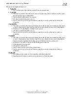
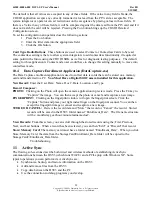
Step 3:
Align the connector on the camera
peripheral module with the edge connector in
the bay and gently press the camera module
into place.
Step 4:
Secure the module by re-fastening
the 2 Philips-head screws.
4.13
Point & Shoot Scanner Peripheral Module
The Point & Shoot Scanner is an optional module for the DSV3 mobile terminals. It is a 1.1 Megapixel
camera that provides high resolution scanning (image capture) for decoding numerous optical
symbologies. It contains enhanced scanning and decoding algorithms and can decode all standard 1
dimensional and common 2 dimensional barcodes. The point & shoot design combined with a wide
angled lens that covers a large scanning area provides quick and easy targeting. There is a comprehensive
SDK that enables rapid custom application development.
The Point & Shoot Scanner is designed for a variety of applications and markets such as:
•
Law Enforcement / Public Safety
•
Military Base Security / Border Control
•
Government / Military ID Processing
•
Seaport Security and Access Control
•
Emergency First Responders
The supported optical symbologies are listed below:
1D Codes 2D
Codes OCR
Code 39
PDF417 (standard)
OCR A (optional)
Code 93
QR Code (optional)
OCR B (optional)
Code 128
Data Matrix (optional)
MICR (optional)
UPC/EAN/JAN
Aztec Code (optional)
Hong Kong 2 of 5
Maxicode (optional)
Interleaved 2 of 5
Micro QR Code (optional)
NEC 2 of 5
Codeblock (optional)
Matrix 2 of 5
Composite Code (optional)
Straight 2 of 5
Code 11
Codabar
MSI Plessey
Pharmacode
DataBarTM
4.13.1
Point & Shoot Scanner Installation Instructions
To install the Point & Shoot Scanner peripheral in the integrated peripheral bay, follow the same steps as
for the Digital Still Camera (DSC) peripheral module (see section 4.12.1).
Screws
Edge
Connector