background image


 SCS1 

Series 

Instruction 

Manual  


92 


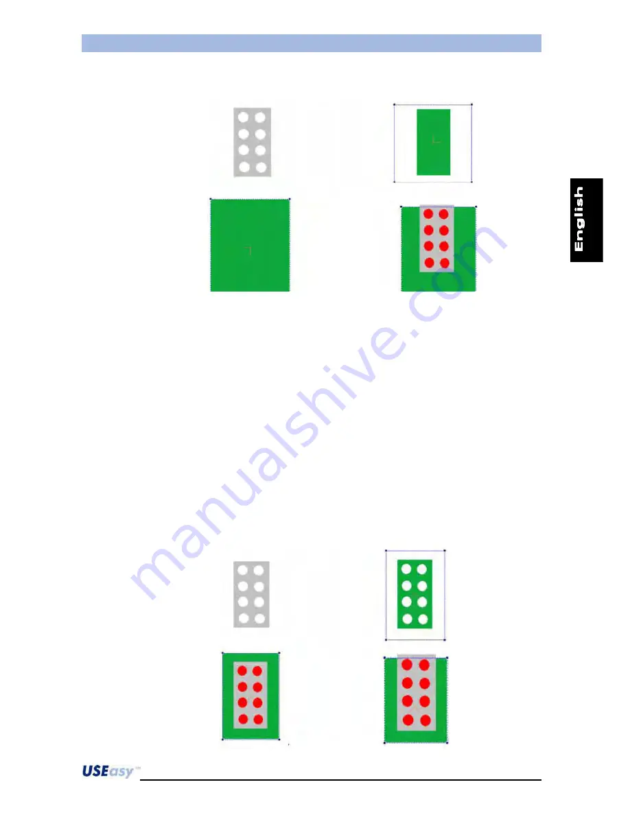
Example: 

grey blister with white pills.


The initial image is always the one on the top left. The result changes modifying tool position and 
parameters. 
 
Top right image: in this case a black object has to be tracked. The object is correctly tracked but the 
pills forming internal perimeters are not considered. 
 
Bottom left image: in this case a white object has to be tracked.  
The tool follows the white object’s background (including completely the blister) and the blob 
tracked is formed by the area enclosed by the tool. Blister and pills form internal perimeters and so 
are not considered.  
 
Bottom right image: a white object has to be tracked. The tool has been drawn to intercepts the top 
side of the blister. Thus the border that characterise the background does not enclose completely 
the blister and pills (also white) are not internal perimeters anymore. In this way pills can be tracked 
as blobs. 
 

Area

: all the characteristics of the same-coloured pixel groups have to be considered to form a blob. 

The internal parts are also tracked. This method provides major precision respect to the previous 
perimeter method, but requires longer elaboration times. 


Example


Phone: 800.894.0412 - Fax: 208.368.0415 - Web: www.ctiautomation.net - e.mail: [email protected]

Phone: 800.894.0412 - Fax: 888.723.4773 - Web: www.clrwtr.com - Email: [email protected]

Phone: 800.894.0412 - Fax: 888.723.4773 - Web: www.clrwtr.com - Email: [email protected]

Phone: 800.894.0412 - Fax: 888.723.4773 - Web: www.clrwtr.com - Email: [email protected]

Содержание SCS1 Series

Страница 1: ... Web www ctiautomation net e mail info ctiautomation net Phone 800 894 0412 Fax 888 723 4773 Web www clrwtr com Email info clrwtr com Phone 800 894 0412 Fax 888 723 4773 Web www clrwtr com Email info clrwtr com Phone 800 894 0412 Fax 888 723 4773 Web www clrwtr com Email info clrwtr com ...

Страница 2: ... 2 JUNE 1997 ELECTROMAGNETIC COMPATIBILITY GENERIC IMMUNITY STANDARD PART 2 INDUSTRIAL ENVIRONMENT CEI IEC 60947 5 2 MARCH 1999 LOW VOLTAGE SWITCHGEAR AND CONTROLGEAR PART 5 CONTROL CIRCUIT DEVICES AND SWITCHING SECTION 2 PROXIMITY SWITCHES Following the provision of the Directive s 89 336 CEE AND SUCCESSIVE AMENDMENTS 92 31 CEE 93 68 CEE Monte San Pietro 12 10 2004 Gianni Stradiotti Quality Assur...

Страница 3: ... regulation Interchangeable optics are supplied as accessories together with integrated and external illuminators that make SCS1 extremely flexible and suitable to many different applications The sensor integrated interface guarantees quick and easy setting of the main basic sensor functions The PC interface allows the user to fully exploit all the more advanced functions of the SCS1 sensor 1 2 Av...

Страница 4: ...mechanical parts Marking control Contour control contour match Component control on PCBs Similarity check with a template Phone 800 894 0412 Fax 208 368 0415 Web www ctiautomation net e mail info ctiautomation net Phone 800 894 0412 Fax 888 723 4773 Web www clrwtr com Email info clrwtr com Phone 800 894 0412 Fax 888 723 4773 Web www clrwtr com Email info clrwtr com Phone 800 894 0412 Fax 888 723 4...

Страница 5: ...f coloured LEDs able to generate both continuous as well as pulsed light with adjustable interval to obtain maximum efficiency external illuminators powered through an M8 connector are available to generate pulsed light ring light spot light back light and laser light Illuminators dedicated to particular applications can be developed upon request Phone 800 894 0412 Fax 208 368 0415 Web www ctiauto...

Страница 6: ...nal trigger signal input M8 connector 3 1 4 2 Strobe GND N C 24Vdc 1 brown 24 Vdc 2 white Not connected 3 blue GND 4 black Strobe TTL signal RJ45 connector This connector is used for sensor and PC communication using Ethernet 10 100 Mbps network Phone 800 894 0412 Fax 208 368 0415 Web www ctiautomation net e mail info ctiautomation net Phone 800 894 0412 Fax 888 723 4773 Web www clrwtr com Email i...

Страница 7: ...le if the SCS1 graphic interface is used Thread optics onto the sensor Power the cable with the M12 8 pole connector Assure that the brown wire pin 2 is connected to the positive 24 Vdc pole and the blue wire pin 7 to the negative pole GND 5 Connect the cable with M12 8 pole connector to the sensor Phone 800 894 0412 Fax 208 368 0415 Web www ctiautomation net e mail info ctiautomation net Phone 80...

Страница 8: ...sing the Ethernet 10 100 Mbps cable Phone 800 894 0412 Fax 208 368 0415 Web www ctiautomation net e mail info ctiautomation net Phone 800 894 0412 Fax 888 723 4773 Web www clrwtr com Email info clrwtr com Phone 800 894 0412 Fax 888 723 4773 Web www clrwtr com Email info clrwtr com Phone 800 894 0412 Fax 888 723 4773 Web www clrwtr com Email info clrwtr com ...

Страница 9: ...pplied with the sensor The following window will appear automatically Figure 1 Note if the CD ROM does not automatically run choose Run from the Start menu and type D setup exe substitute the appropriate drive letter of your CD ROM drive for D and press Enter The guided installation of the software will begin selecting Install SCS1 Graphic User Interface Follow then the installation instructions p...

Страница 10: ...ress 172 27 101 209 Subnet mask 255 255 0 0 3 3 1 PC configuration The following steps have to be followed to configure correctly the PC 1 Open the Network Neighbourhood clicking the desktop icon Figure 2 and select Properties Figure 2 or alternatively use the following route Start Æ settingsÆ control panel Double click Networks and Dial up connections and the following window will show up Figure ...

Страница 11: ...lick OK to confirm IP address 172 27 101 1 Subnet mask 255 255 0 0 Phone 800 894 0412 Fax 208 368 0415 Web www ctiautomation net e mail info ctiautomation net Phone 800 894 0412 Fax 888 723 4773 Web www clrwtr com Email info clrwtr com Phone 800 894 0412 Fax 888 723 4773 Web www clrwtr com Email info clrwtr com Phone 800 894 0412 Fax 888 723 4773 Web www clrwtr com Email info clrwtr com ...

Страница 12: ...c value of the selected field can be changed A continuous pressure on the push button allows to proceed more rapidly Press SET to confirm changes Figure 6 6 Once checked all 4 fields of the sensor s IP address scroll down the menu until the text is visualised on the display Press SET to return to communication parameter configuration menu 7 Scroll down menu using or until the text is visualised Pr...

Страница 13: ...he IP address On the contrary if the PC is connected to the sensor using a local LAN network intrinsic constraints regarding the existing network configuration have to be respected For this reason the sensor s IP address can be changed using push buttons and thus guaranteeing improved system flexibility If the PC s IP address is unknown the user can find it as follows 1 open a DOS window from the ...

Страница 14: ...ect The default parameters are The IP address refers to the IP address associated to the sensor The programme will try to connect itself to the sensor Two situations can occur correctly connected sensor the main programme window is visualised and the operating functions of the on line mode are activated connected sensor and wrong communication parameters the sensor does not respond Phone 800 894 0...

Страница 15: ...previously saved by the sensor and saved on the PC or on any other compatible image bitmap format with 256 grey levels 640x480 or 320x240 resolution The off line mode can be accessed by clicking on Off line instead of Connect after starting the programme The off line mode offers all the options necessary for an inspection configuration naturally with the exception of acquiring new images and check...

Страница 16: ...re a high quality image where the target object presents well defined edges and evident main characteristics choose carefully the tools to use for the elaboration to guarantee the best result possible in the easiest manner particularly in the software inspection where a wider range of tools is available regulate precisely the parameters of the tools selected test the inspection choices made on dif...

Страница 17: ...ring the following options Setup allows to access the parameters that control sensor functioning and inspection process Registers visualises and modifies the numeric values of the tool parameters set using the PC interface in the 16 sensor registers Teach in self acquisition process necessary to acquire the template used for comparison during inspection Save allows to save inspection and automatic...

Страница 18: ...us Setup Registers Pass Fail Threshold adjustment BKGD Acquisition Teach in Save Target Acquisition Run Esc 4 2 2 Sensor configuration diagram Figure 8 Phone 800 894 0412 Fax 208 368 0415 Web www ctiautomation net e mail info ctiautomation net Phone 800 894 0412 Fax 888 723 4773 Web www clrwtr com Email info clrwtr com Phone 800 894 0412 Fax 888 723 4773 Web www clrwtr com Email info clrwtr com Ph...

Страница 19: ...f failure In both cases press SET to return to previous menu Select to focus the image The user has to act on the sensor optics to increase the number that appears on the display Press SET to return to previous menu Select to choose the necessary resolution The possible resolutions are given below VGA 320x240 pixels full VGA 640x480 pixels exit from resolution setting submenu Scroll down the optio...

Страница 20: ...ied in the Register menu refer to specific section at page 54 The numeric value can be modified choosing the specific register The register parameter type association e g reg1 blob count threshold is not expressed in the register menu but has to be remembered by the user that has set the current inspection To change the value of a register press The current register value is visualised To change t...

Страница 21: ...ted to the parameter e g register 2 4 The R2 text will appear inside the grey box signalling that the parameter has been associated to register 2 Phone 800 894 0412 Fax 208 368 0415 Web www ctiautomation net e mail info ctiautomation net Phone 800 894 0412 Fax 888 723 4773 Web www clrwtr com Email info clrwtr com Phone 800 894 0412 Fax 888 723 4773 Web www clrwtr com Email info clrwtr com Phone 80...

Страница 22: ... point of the position vector with the edge to register 1 The angle value formed by the direction vector of the shape tool with the horizontal axis to register 2 The length value of the tool vector to register 3 The thickness value to register 4 The search threshold value to register 5 The barycentre value to register 6 The absolute threshold value to register 7 X in register 0 Y in register 1 Bar...

Страница 23: ... so return to main menu 4 2 5 Teach in setting The device self acquisition or Teach in is activated by selecting TEAC The following operations are sequential The user proceeds step by step pressing SET Step 1 BAC Background acquisition Press SET to acquire background and pass to next step Step 2 TARG Reference image acquisition Position target object in front of the sensor and press SET to acquire...

Страница 24: ...equence The inspection can now be saved or exit from the menu pressing respectively SAVE or ESC using or The sensor is now configured and inspection can begin If it s necessary press S_In to make the inspection run Phone 800 894 0412 Fax 208 368 0415 Web www ctiautomation net e mail info ctiautomation net Phone 800 894 0412 Fax 888 723 4773 Web www clrwtr com Email info clrwtr com Phone 800 894 04...

Страница 25: ...ion creation for advanced users all the available options are active and the user has complete freedom in developing inspections Wizard guided new inspection creation recommended to new users the SCS1 graphic interface suggests some steps to follow and guides the user in the creation of a new inspection Main menu Toolbar Toolbox Parameters Graph Operation list Status bar Phone 800 894 0412 Fax 208...

Страница 26: ...ut during each operating status Live mode Setup mode Run mode 1 Target positioning 1 Trigger selection Tool check 2 Resolution selection 2 Locator insertion Monitor mode 3 Lighting check 3 Control insertion Inspection time check 4 Exposure time 4 Analysis tool insertion Test Mode 5 Image focussing 5 Test insertion Visualises the last image saved showing the tool status 6 Test image saving 6 Serial...

Страница 27: ...or is disconnected from the PC or runs in Monitor mode Phone 800 894 0412 Fax 208 368 0415 Web www ctiautomation net e mail info ctiautomation net Phone 800 894 0412 Fax 888 723 4773 Web www clrwtr com Email info clrwtr com Phone 800 894 0412 Fax 888 723 4773 Web www clrwtr com Email info clrwtr com Phone 800 894 0412 Fax 888 723 4773 Web www clrwtr com Email info clrwtr com ...

Страница 28: ...aspects concerning the quality of the acquired image have to be optimised This is a key operation to guarantee the success of the application 2 Positioning Position the target object inside the field of view 3 Resolution Select the resolution of the image to visualise Different resolutions are available VGA 640x480 pixel and VGA 320x240 pixel A larger working field is obtained by selecting VGA whi...

Страница 29: ...r 7 Acquisition mode Configures the reference image using the trigger hardware if set in the trigger mode For example if a dynamic scene is controlled a particular phase is difficult to obtain by pressing the saving the reference image icon The acquisition of the reference image in the trigger mode and using a trigger hardware has to be set and then save the singular phases of the inspected scene ...

Страница 30: ...s completed Live mode panel parameters Outputs Resolution Exposure time Gain Focussing indicators Reference image saving Autoexposure Trigger parameters Integrated external illuminator activation Strobe activation Elaborated image saving Phone 800 894 0412 Fax 208 368 0415 Web www ctiautomation net e mail info ctiautomation net Phone 800 894 0412 Fax 888 723 4773 Web www clrwtr com Email info clrw...

Страница 31: ...out an inspection operating step and the entry order establishes the execution order during the elaboration The tools are divided in three groups Locators Control and Analysis Theoretically this should also represent the insertion order even if it is only a logical sequence followed in most cases The only really fundamental tool is the Test tool The Test result in fact guides the device outputs Ph...

Страница 32: ...ving the cursor with the mouse Set the ends of the dashed line by pressing first end and then releasing the left button of the mouse second end Select the variation type that has to be tracked from white to black in the example provided To begin inspection the Software trigger has to find an edge on the dashed line What is an Edge a variation of the brightness between adjacent pixels that presents...

Страница 33: ...p side of the blister 13 Control insertion In the following example the Blob count tool is used for tablet counting After selecting the tool the user has to draw a rectangle around the blister What is a Blob The image has 256 possible grey shades 0 black 255 white The Blob count sets automatically a threshold denominated Binarization and distinguishes white pixels brightness higher than the thresh...

Страница 34: ...s found are coloured green To overcome this situation the user can limit the blob size By doing this unwanted blobs are discarded and the tablets usually of the same size are counted Blob count Phone 800 894 0412 Fax 208 368 0415 Web www ctiautomation net e mail info ctiautomation net Phone 800 894 0412 Fax 888 723 4773 Web www clrwtr com Email info clrwtr com Phone 800 894 0412 Fax 888 723 4773 W...

Страница 35: ... area The blobs generated by the background and noise are marked in red they are still recognised as blobs but they are discarded as they do not respect specifications The counting result is thus 12 During this process the operating status is a Failure as the operating status OK failure omitting Error for the moment is determined comparing the counting result 12 and the Count parameter value 1 by ...

Страница 36: ... on the toolbar icon or select Save from the File menu and assign a name when requested Toolbar Menu Phone 800 894 0412 Fax 208 368 0415 Web www ctiautomation net e mail info ctiautomation net Phone 800 894 0412 Fax 888 723 4773 Web www clrwtr com Email info clrwtr com Phone 800 894 0412 Fax 888 723 4773 Web www clrwtr com Email info clrwtr com Phone 800 894 0412 Fax 888 723 4773 Web www clrwtr co...

Страница 37: ...e the inspection saving is desired and click on OK 16 Functioning check of tools used Terminated the Setup phase the user can pass in Run mode and control if the inspection is carried out correctly To access the Run mode the user has to select the toolbar icon or select Run from the Mode menu Toolbar Menu Phone 800 894 0412 Fax 208 368 0415 Web www ctiautomation net e mail info ctiautomation net P...

Страница 38: ...The sensor elaborates the acquired images and transmits the results obtained to the PC The images acquired are not visualised on the screen but the results are given in a text format During sensor functioning tool information about status results and execution time is visualised The user has to save an inspection on the sensor before passing to the Monitor mode and so activating the elaboration Th...

Страница 39: ...oolbar Menu Seven steps have to be carried out Step 1 Live regulation of parameters relative to image acquisition and saving of reference image Step 2 Inspection type selection Step 3 Trigger selection Step 4 Locator selection Step 5 Locator positioning Step 6 Control positioning Step 7 Output selection Phone 800 894 0412 Fax 208 368 0415 Web www ctiautomation net e mail info ctiautomation net Pho...

Страница 40: ...spection elaboration phase Two different inspection resolutions can be selected 640x480 or 320x240 that respectively favour the dimensions of the area acquired by the sensor and the elaboration speed Autoexposure click on Autoexpose to run the automatic regulation process of the sensor exposure time Focussing to maximise focus turn the sensor lens ring The focus level is visualised on the right si...

Страница 41: ...bject analysing the contour Saved the target object contour an object with a similar contour is tracked inside the working area Area analysis Recognises an object checking area perimeter and other geometrical characteristics Pattern match Recognises an object comparing it with the target object The comparison involves each single pixel evaluating brightness differences between the template and the...

Страница 42: ...tware trigger is represented graphically by a dashed line where an arrow indicates the elaboration direction This line identifies also the part of image elaborated The full inspection runs only when a light variation appears along the line due to the passage from white zones to black zones and vice versa Typically this condition occurs when the target object passes through object must have a suffi...

Страница 43: ...e used in the successive steps as relative reference system s origin Pattern match locator Pattern match consists in checking the similarity between a template and a target object The Pattern match locator tracks a target object inside a specific area and sets the position The locator is represented graphically by two rectangles one inside the other that respectively form the tracking area externa...

Страница 44: ...nd of the sequence the user can modify the locator parameters present on the panel on the right side of the window Click on Next to continue Phone 800 894 0412 Fax 208 368 0415 Web www ctiautomation net e mail info ctiautomation net Phone 800 894 0412 Fax 888 723 4773 Web www clrwtr com Email info clrwtr com Phone 800 894 0412 Fax 888 723 4773 Web www clrwtr com Email info clrwtr com Phone 800 894...

Страница 45: ...r control positioning At the end of the sequence the user can modify the control parameters present on the panel on the right side of the window Click on Next to continue Contour match Area analysis Pattern match Object count Measurement Phone 800 894 0412 Fax 208 368 0415 Web www ctiautomation net e mail info ctiautomation net Phone 800 894 0412 Fax 888 723 4773 Web www clrwtr com Email info clrw...

Страница 46: ...ided creation is ending by clicking on Next and the user can save the inspection obtained Phone 800 894 0412 Fax 208 368 0415 Web www ctiautomation net e mail info ctiautomation net Phone 800 894 0412 Fax 888 723 4773 Web www clrwtr com Email info clrwtr com Phone 800 894 0412 Fax 888 723 4773 Web www clrwtr com Email info clrwtr com Phone 800 894 0412 Fax 888 723 4773 Web www clrwtr com Email inf...

Страница 47: ...ts SCS1 INIT boot 5 2 Factory configuration reloading During initialisation there is the chance to reload the factory configuration Press and push buttons at the same time when the display visualises text Keep them pressed until text is visualised and then for 3 seconds at lest to start the factory configuration reloading process When the system reset is over the display will visualise text Output...

Страница 48: ...g images for the inspection elaborated on the PC err error presence Note during functioning the sensor automatically carries out a selected inspection As default this inspection is the one in the first memory slot All the inspections stored in the sensor can be selected but only using the SCS1 Graphic User Interface via PC Phone 800 894 0412 Fax 208 368 0415 Web www ctiautomation net e mail info c...

Страница 49: ...ask Save Esc Network S_IN M A I N M E N U S U B M E N U Direct Reverse Esc Display Run reg0 reg1 reg2 reg3 reg16 Save Esc Illuminator Autoexposure Focus Resolution Trigger Mode Output Save Esc Status Setup Registers Pass Fail Threshold adjustment BKGD Acquisition Teach in Save Target Acquisition Run Esc Phone 800 894 0412 Fax 208 368 0415 Web www ctiautomation net e mail info ctiautomation net Pho...

Страница 50: ...Save display visualises the SAVE text allows the user to save the configured inspection Network display visualises the NETS text allows to access the sensor communication parameters Display display visualises the DISP text allows to change display text orientation Start inspection display visualises the S_IN text allows to start inspection The user can scroll down the other options using the and p...

Страница 51: ... submenu while others carry out functions The user can exit from the submenus in two manners pressing SET while display visualises ESC Exit The configuration is left unchanged pressing SET on any other option the selection is saved Phone 800 894 0412 Fax 208 368 0415 Web www ctiautomation net e mail info ctiautomation net Phone 800 894 0412 Fax 888 723 4773 Web www clrwtr com Email info clrwtr com...

Страница 52: ...o Setup menu or to try again if the operation failed Note to carry out correctly the autoexposure process the target object must be placed in the inspection area simulating the operating conditions Light on integrated illuminator activation Light off integrated illuminator deactivation Exit returns to main menu without changing configuration Phone 800 894 0412 Fax 208 368 0415 Web www ctiautomatio...

Страница 53: ... characterised by near text and symbol Turning the ring making closer the reference notch and near the sensor will progressively focus a closer plane Turning the ring making closer the notch and the sensor will progressively focus a further plane 5 6 4 Resolution Two resolutions are available Full VGA 640x480 pixels VGA 320x240 pixels VGA Full VGA Exit returns to previous menu without changing con...

Страница 54: ...ging configuration Filter short pulses due to disturbances can appear and can be confused with trigger signals To avoid unwanted acquisitions the user can set a minimum trigger pulse duration and so shorter pulses will not be considered A number representing the minimum trigger pulse duration will appear by selecting FILT in ms The minimum trigger duration can be varied using the and push buttons ...

Страница 55: ...g Teach in when target object acquisition is requested the user must position in the sensor inspection area a number of objects equal to the saved number Example 3 is set as the number of objects to count The inspection parameters are configured and user enters in Teach in The background is acquired and then the target object Supposing that the object to count is a tap and 3 are the taps that I ex...

Страница 56: ...se the output will be deactivated as the sensor expects to find 3 stamps If 3 stamps are instead positioned in the inspection area only during the threshold regulation not during the acquisition phase the output is activated and can thus switch The number can be changed by pressing on the and push buttons Press SET to confirm Contour match Compares the template with the target object according to ...

Страница 57: ...he register value otherwise to discard changes press The sequence is repeated for each value register to be modified Use and to modify the value Phone 800 894 0412 Fax 208 368 0415 Web www ctiautomation net e mail info ctiautomation net Phone 800 894 0412 Fax 888 723 4773 Web www clrwtr com Email info clrwtr com Phone 800 894 0412 Fax 888 723 4773 Web www clrwtr com Email info clrwtr com Phone 800...

Страница 58: ...owever the possibility of changing the sensor sensitivity to distinguish or not an object Once acquired the information relative to the target object the sensor recognises the object and consequently the yellow Output 1 LED turns on indicating inspection success The threshold can now be lowered until the LED turns off The threshold has become so narrow that even the target object is no longer reco...

Страница 59: ...e changes made and returns to main menu Exit returns to previous menu without changing configuration 5 10 1 IP address The sensor s IP address can be visualised and configured by pressing SET while on IP_A Phone 800 894 0412 Fax 208 368 0415 Web www ctiautomation net e mail info ctiautomation net Phone 800 894 0412 Fax 888 723 4773 Web www clrwtr com Email info clrwtr com Phone 800 894 0412 Fax 88...

Страница 60: ...when text is visualised to return to the Network menu and decide whether save the new configuration or not Note the changes made are effective only after sensor re booting 5 10 2 Net mask The Net mask can be configured by selecting The process is similar to the IP address configuration Press and to change the number Phone 800 894 0412 Fax 208 368 0415 Web www ctiautomation net e mail info ctiautom...

Страница 61: ... 10 4 Start inspection Press SET to enter in Run mode without saving the parameter changes Phone 800 894 0412 Fax 208 368 0415 Web www ctiautomation net e mail info ctiautomation net Phone 800 894 0412 Fax 888 723 4773 Web www clrwtr com Email info clrwtr com Phone 800 894 0412 Fax 888 723 4773 Web www clrwtr com Email info clrwtr com Phone 800 894 0412 Fax 888 723 4773 Web www clrwtr com Email in...

Страница 62: ...Status bar panel containing some general information such as the system operating status selected tool status cursor coordinates Operating steps this table indicates all the operating steps belonging to an inspection The tool name tool type operating status OK Failure Error and the numeric result are highlighted for each operating step Parameters panel containing parameters relative to the selecte...

Страница 63: ... programming running through the following window The On line mode is selected by clicking on Connect The Off line mode is selected by clicking on Off line Please refer to paragraphs 3 3 3 4 for further details concerning the IP Address and connection problems The user can change mode at any time using the toolbar or menu Toolbar Menu Phone 800 894 0412 Fax 208 368 0415 Web www ctiautomation net e...

Страница 64: ... sensor are visualised on the image panel in real time In this operating mode the user can modify all the image parameters in order to optimise quality Live mode options Parameters Advanced Outputs Resolution Illuminators Output1 mode Exposure time Trigger Output2 mode Gain Image saving Focus level Reference image Phone 800 894 0412 Fax 208 368 0415 Web www ctiautomation net e mail info ctiautomat...

Страница 65: ...ult to obtain by pressing the saving the reference image icon The acquisition of the reference image in the trigger mode and using a trigger hardware has to be set and then save the singular phases of the inspected scene until reaching the necessary configuration In this case pressing saving the reference image and providing another trigger pulse a particular image can be saved as our template Ref...

Страница 66: ...g ones following a FIFO logic the oldest image is replaced by the latest image Outputs Two digital outputs offer inspection information These outputs can be configured as follows Normal functioning output switches according to inspection results OK Failure if tools have been correctly configured Toggle mode output switches at each inspection cycle completion Image saving The currently visualised i...

Страница 67: ... in the sensor memory and are available for the Test mode The following steps indicate how to access the images once saved Ensure that during the Setup phase the image saving option has been selected Run inspection on the sensor disconnected from PC to elaborate images Re connect sensor and upload the inspection from the sensor clicking on the toolbar icon or select Open from the sensor menu Selec...

Страница 68: ...inspection must be saved on file after loading the images from the sensor In this manner the user can access the test images each time the inspection is re opened 6 2 4 Run mode The PC processes in real time the images acquired by the sensor In this operating mode the sensor only acquires images The operating steps can not be selected or modified NOTE if you set up the hardware trigger you must gi...

Страница 69: ... icon The following example should better clarify this mode 1 An inspection is set even without saving the images in the Advanced menu of the Live mode using a Locator or Control tool If the images has to be saved only when the tool chosen fails as in the example a logic tool has to be used to carry out the not status of the operator tool 2 The Image saving tool can be set associating it the tool ...

Страница 70: ...rom telecamera icon In this case the inspected object has been moved and thus the Edge locator fails and the logic operator enters in the OK status The image currently elaborated and visualised is saved clicking on the icon Phone 800 894 0412 Fax 208 368 0415 Web www ctiautomation net e mail info ctiautomation net Phone 800 894 0412 Fax 888 723 4773 Web www clrwtr com Email info clrwtr com Phone 8...

Страница 71: ...ts and execution time is visualised The user has to save an inspection on the sensor before passing to the Monitor mode and so activate the elaboration NOTE if you set up the hardware trigger you must give trigger impulses in order to process images Phone 800 894 0412 Fax 208 368 0415 Web www ctiautomation net e mail info ctiautomation net Phone 800 894 0412 Fax 888 723 4773 Web www clrwtr com Ema...

Страница 72: ... Open opens an existing inspection Save saves a inspection on sensor memory Parameters provides access to sensor parameters Diagnostics provides access to the sensor diagnostics Sensor info provides access to default sensor information The current inspection inspection that also runs automatically at powering and serial port can be configured by selecting Parameters Here you can also configuring t...

Страница 73: ...ble for test The image can be an acquired image or a Bitmap file with 648x480 or 320x240 resolution grey scale image Save image saves current image on file in a Bitmap format Inspection Load reference image a previously acquired and saved image can be used as a reference image Inspection parameters provide access to inspection parameters The parameters available also in Live mode can be accessed a...

Страница 74: ...gramme enters in the Test mode from telecamera Monitor programme enters in the Monitor mode Options Preferences provides access to preference menu Update Firmware runs firmware update Debug file download saves the debug file on the PC according to the debug set Language selects graphic interface language Phone 800 894 0412 Fax 208 368 0415 Web www ctiautomation net e mail info ctiautomation net Ph...

Страница 75: ... with the new version to be saved The new SCS1 version offers new controls to ease the firmware update procedure The new controls concern the impossibility to update a particular SCS1 model e g RS232 with a different firmware model e g RS485 as shown in the following image A control on the same firmware version has been added including a warning during the update of a SCS with a firmware version p...

Страница 76: ...ckage extension of the firmware updated will no longer have the fw ending but the dfu extension Help Guide opens programme s help on line Information contextual information 6 3 2 Toolbar Phone 800 894 0412 Fax 208 368 0415 Web www ctiautomation net e mail info ctiautomation net Phone 800 894 0412 Fax 888 723 4773 Web www clrwtr com Email info clrwtr com Phone 800 894 0412 Fax 888 723 4773 Web www ...

Страница 77: ...ction from sensor Connect disconnect Setup mode Run mode Cancel operating step New Inspection Wizard Save inspection on PC Test mode Save inspection on the sensor Live mode Monitor mode Save image Test mode from telecamera Phone 800 894 0412 Fax 208 368 0415 Web www ctiautomation net e mail info ctiautomation net Phone 800 894 0412 Fax 888 723 4773 Web www clrwtr com Email info clrwtr com Phone 80...

Страница 78: ...ur different inspections To save the inspection on the sensor the user has to simply click on the toolbar icon or select Save from the sensor menu The program will request PC saving if not previously done This procedure is recommended but not compulsory Toolbar Menu The following window is visualised Select the memory slot where the inspection saving is desired and click on OK Phone 800 894 0412 F...

Страница 79: ...hically a software tool that conditions the elaboration of the acquired images The image acquisition and elaboration cycle is similar to the Continuous mode but with one difference Acquired the image the sensor has to be satisfy the condition established by the Software trigger before completing the elaboration The condition is usually connected to the position of the target object In this manner ...

Страница 80: ... The user can use one Software trigger that automatically becomes the first inspection operating step Example Continuous mode Software trigger comparison Supposing to configure an inspection that lasts 100 ms using the Software trigger The time necessary to acquire an image is about 30 ms The Software trigger elaboration time is about 5 ms The remaining 65 ms are dedicated to image elaboration e g...

Страница 81: ...ysed is the right image to inspect 2 Continuous mode No elaboration condition has to be respected and the images are all acquired and elaborated Obviously not all the images acquired are meaningful For example the first and the third would generate an inspection failure even in presence of a valid object However the Continuous mode is very useful during functioning verification of a recently confi...

Страница 82: ...tic tool selects automatically which variation to distinguish Direction determines the direction of the elaboration from start to end elaboration starts from the first end and continues towards the arrow from end to start elaboration starts from the arrow and continues towards the first end opposite to the arrow s direction Please refer to Edge locators paragraph for further details Phone 800 894 ...

Страница 83: ... carries out specific operations and the user can configure the relative specifications e g distance measurement area surface If the specifications are not respected the tool status generates Failure If the measurement is not carried out the tool status generates an Error The Error status can have different causes Position the cursor using the mouse on the Error text Figure 20 to visualise the cod...

Страница 84: ... in the Edge locator indicated in the figure the ROI consists in a blue line that represents the locator Area ROI the Blob locator shown in the figure is represented by a blue rectangle The ROI in this case is the entire surface included in the rectangle Reference system all tools are referred either to an absolute reference system or to a relative reference system connected to the tool used previ...

Страница 85: ...graph to visualise a tooltip window containing the relative information Edge detection graph Figure 21 and 22 represent respectively an Edge locator and the associated graph The graph is divided as follows Red profile pixel s brightness distribution along the elaboration line The tooltip parameter Absolute supplies the brightness numeric value Green profile noise filtered brightness distribution T...

Страница 86: ...between 0 black and 255 white The values indicated on the right refer to the intensity derivative Blob analysis graph Figure 23 and 24 represent respectively a Blob count and the associated graph The graph is divided are follows Abscissa axis indicates the entire greyscale 0 255 The tooltip parameter Brightness refers to the grey tone of the mouse cursor s position Ordinate axis indicates the numb...

Страница 87: ... The edge point is practically the boundary between two areas characterised by different brightness e g white objects on black background Once located the edge position it can be used as a reference for other locators or measurement tools Positioning refers to Software trigger The Edge locator differently from the Software trigger is represented by a continuous line Once specified the edge type to...

Страница 88: ...xis Variation type two edge types can appear one due to the transition from a dark to a bright area positive edge and one due to the transition from a bright to a dark area negative edge from white to black only negative edges are considered from black to white only positive edges area considered both both edges are considered automatic tool selects automatically which variation to distinguish Dir...

Страница 89: ...d to calculate the barycentre According to the threshold value a line parallel to the abscissa axis is drawn The area considered for the barycentre calculation is included between the line and the curve E g peak value 100 barycentre threshold 40 A line parallel to the X axis at a 40 height is drawn The area included between the line and the curve is used to calculate the barycentre Constraints the...

Страница 90: ...ge Results top left vertex coordinates of the located object status relative reference system graphic representation with origin in the top left side of the object Parameters X Y top left ROI coordinates Height rectangle height delimiting the ROI Thickness thickness of each locator Width rectangle width delimiting the ROI Variation type edge type tracked by the locators that form the Composite loc...

Страница 91: ...he selection of the blob type to isolate the locator tracks inside the ROI the larger blobs The figure indicates how the locator starting from the top image locates blobs with dark pixels selected previously The largest blob is highlighted in green while smaller blobs in red are discarded Established the binarization threshold and pixel type to consider white or black the image part that does not ...

Страница 92: ...ack object white object Binarization threshold value of the threshold used to distinguish light coloured pixels from the dark ones during image passage from greyscale in black and white Pixels with a value superior to the threshold result to be white after binarizzation those with an inferior value black The threshold is calculated automatically when the tools are inserted To fix it manually the u...

Страница 93: ...ed blob area plus 10 Blob formation selects the method used to form blobs Two options are possible Perimeter tool carries out binarization inside the tracking area and follows the border of the selected objects white or black The borders characterised by closed lines are considered valid and the entire internal area forms the blob Internal perimeters are not considered For example if the black tar...

Страница 94: ...s to be tracked The tool has been drawn to intercepts the top side of the blister Thus the border that characterise the background does not enclose completely the blister and pills also white are not internal perimeters anymore In this way pills can be tracked as blobs Area all the characteristics of the same coloured pixel groups have to be considered to form a blob The internal parts are also tr...

Страница 95: ...ted according to inspection timing as well as the results to reach Phone 800 894 0412 Fax 208 368 0415 Web www ctiautomation net e mail info ctiautomation net Phone 800 894 0412 Fax 888 723 4773 Web www clrwtr com Email info clrwtr com Phone 800 894 0412 Fax 888 723 4773 Web www clrwtr com Email info clrwtr com Phone 800 894 0412 Fax 888 723 4773 Web www clrwtr com Email info clrwtr com ...

Страница 96: ...raw a rectangle enclosing the target object after confirming the position by clicking on the left mouse button an external rectangle will appear automatically representing the tracking area The position and dimension of the two rectangles can be changed but not the rotation direction Results rectangle s top left vertex coordinates enclosing the target object X Y status Parameters The parameter are...

Страница 97: ...ection phases The locator is positioned on the window drawing a line which represents a reference Edge locator around which a rectangle is designed dimensions can be changed using the mouse The rectangle represents the elaborated area around the reference Edge Locator a certain number of parallel Edge locators is positioned automatically but not graphically visualised The number of Edge locators d...

Страница 98: ...angle between the line parallel to X axis of the absolute reference system passing through the edge tracked by the central Edge locator and the line identified by the segment interpolated by the tracked edges Angle Please refer to example given below coordinates of the edge tracked by the central Edge locator reference system graphic representation with origin in the central edge point and angle r...

Страница 99: ...e the window part on the left side of the observer is the bottom one The measured angle is 45 To complete the example figure 27 represents the same object and the Inclinometer is rotated by 180 The part of the window that was on the left side of the observer is now on his right side and vice versa Starting form the line parallel to the X axis the locator has to arrive to the segment part on the to...

Страница 100: ...t to end elaboration starts from the first end and continues towards the arrow from end to start elaboration starts from the arrow and continues towards the first end opposite to the arrow s direction Points this parameter specifies the number of edge points the tool tracks and will be used to obtain the interpolated segment Consequently the parameter establishes the number of Edge locators used I...

Страница 101: ...racked by two Inclinometer locators Positioning none the user just has to assign the name of the two reference operators Results coordinates of intersection point X Y reference system graphic representation with origin in the intersection point relative reference system angle equal to the first operator angle Angle Parameters Only the parameters identifying the two reference locators can be specif...

Страница 102: ...ges present in the control direction refer to Edge locator at page Errore Il segnalibro non è definito for more detailed information The result obtained however can not be used as a relative reference system for the successive phases differently from Edge locator result Specified the edge type to track positive or negative or both the tool elaborated the ROI detected by the line and tracks all edg...

Страница 103: ...ype two edge types can appear one due to the transition from a dark to a bright area positive edge and one due to the transition from a bright to a dark area negative edge from white to black only negative edges are considered from black to white only positive edges area considered both both edges are considered automatic tool selects automatically which variation to distinguish Direction determin...

Страница 104: ...eshold is expressed in percentage of the peak value and determines the area considered to calculate the barycentre According to the threshold value a line parallel to the abscissa axis is drawn The area considered for the barycentre calculation is included between the line and the curve E g peak value 100 barycentre threshold 40 A line parallel to the X axis at a 40 height is drawn The area includ...

Страница 105: ...ols Refer to Intersection locator for further details The result obtained however can not be used as a relative reference system for the successive phases differently from Intersection locator result Parameters Refer to Intersection locator 6 8 4 Inclinometer Description similar to the Inclinometer locator as it evaluates the object angle respect to the X axis Refer to Inclinometer locator for fur...

Страница 106: ...arameters X coordinate that identifies the horizontal position of the first locator point Y coordinate that identifies the vertical position of the first locator point Length ROI length Thickness elaboration area thickness Angle expressed in degrees calculated according to the tool rotation respect to the X axis Variation type from white to black only negative edges are considered from black to wh...

Страница 107: ...f values accepted during inspection Example Position the Internal caliper on the reference image during Setup The tool carries out the elaboration and calculates a distance In our example the distance is 100 pixel and the tolerance is 10 During inspection the range of accepted distance values is Value range Setup distance 10 Setup distance Setup distance 10 Setup distance Value range 100 10 100 10...

Страница 108: ...old value of the threshold used to distinguish light coloured pixels from the dark ones during image passage from greyscale in black and white Pixels with a value superior to the threshold result to be white after binarizzation those with an inferior value black The threshold is calculated automatically when the tools are inserted To fix it manually the user has to click on the icon on the left of...

Страница 109: ...m value can be used to filter the background Perimeter minimum and maximum accepted perimeters The parameter is calculated as follows Transitions along X axis transitions along Y axis diagonal transition x 2 The perimeter supplies additional information on the target object Objects with the same area may have different parameters Area perimeter minimum and maximum value accepted in the area perime...

Страница 110: ...dium grey levels Accepted values 0 255 Bounding box width height BB this is a rectangle with a top left vertex has coordinates that coincide with the minimum X and minimum Y and a bottom right vertex has coordinates that coincide with the maximum X and maximum Y It is practically a rectangle with the smallest area possible able to contain the entire blob A control on the object position is made by...

Страница 111: ...he ROI Width rectangle width delimiting the ROI Object type specifies the blob type to track black object white object Binarization threshold value of the threshold used to distinguish light coloured pixels from the dark ones during image passage from greyscale in black and white Pixels with a value superior to the threshold result to be white after binarizzation those with an inferior value black...

Страница 112: ...two objects have to resemble each other to guarantee a positive result Difference 0 Æ the two objects have to be identical Difference 1000 Æ differences are tolerated Note if the difference constraints are both zero the result is always OK Register threshold association Phone 800 894 0412 Fax 208 368 0415 Web www ctiautomation net e mail info ctiautomation net Phone 800 894 0412 Fax 888 723 4773 W...

Страница 113: ...anced parameters Quality speed inspection precision and timing can be changed by using the mouse cursor Higher the quality the higher the inspection precision but the longer the inspection time Higher the speed and shorter the elaboration time but the lower the inspection precision Difference threshold parameter that takes in account the difference between the template and target object to inspect...

Страница 114: ...trols can be carried out using for example a distance locator and tool and setting accordingly the minimum and maximum distance parameters Minimum maximum distance minimum maximum value accepted If the distance is bigger the operating status is Failure Tolerance parameter that can be used as an alternative to the distance constraints The tool is positioned graphically on the image during Setup and...

Страница 115: ...ring inspection 6 9 3 Comparatore Description compares the results of the other tools e g Caliper or the numeric values through a major minor or equal comparison control Positioning none the user just has to assign the name of the two reference tools Parameters Operator1 first reference tool value Operator2 second reference tool value Function Comparison of operator1 respect to operator2 Compariso...

Страница 116: ...he Logic tool replaces the Test tool and extends the and or logic functions offering upto 5 inputs Differently from the Test tool this tool doesn t consent the association of the result with one of the sensor outputs due to the presence of a specific function refer to section relative to the digital output Positioning none the user just has to assign the name of the reference tools Selection of nu...

Страница 117: ... OK OK OK OK Failure OK OK OK Failure Failure Failure Failure Xor restores an OK status only if one tool has an OK status XOR status Operator I status Operator II status Failure OK OK OK Failure OK OK OK Failure Failure Failure Failure Nand restores an OK status when not all tools has an OK status Nand status Operator I status Operator II status Failure OK OK OK Failure OK OK OK Failure OK Failure...

Страница 118: ...ure Failure OK Failure OK Failure OK Failure Failure Positioning none the user just has to assign the name of the reference tools and the operation to carry out Parameters Operator1 5 first reference tool s Functions logic tool selected Function Tools Phone 800 894 0412 Fax 208 368 0415 Web www ctiautomation net e mail info ctiautomation net Phone 800 894 0412 Fax 888 723 4773 Web www clrwtr com E...

Страница 119: ...of the grey ROI tool levels when ordered in an ascending descending order Average value the value obtained from the mathematic average of the grey ROL tool levels Minimum value the inferior value of the grey ROL tool levels Maximum value the highest value of the grey ROL tool levels Average percentage value the value obtained from the arithmetic average of the grey levels once eliminated the grey ...

Страница 120: ...acterised by environmental conditions with a high light variation on the controlled area These situations tools using binarizzation algorithms are not very effective as they function in absence of light variation Consequently if this tool is used together with the Blob Count Blob Locator Contour Match tools the inspections become more reliable Note the use of this tool becomes useless if used with...

Страница 121: ... 00 255 00 181 00 Pattern Match locator nome_op result X Y angle pattern_match 0 158 00 221 00 00 003 Controls Edge name_op result X Y angle edge 0 325 00 359 94 90 00 Intersection name_op result X Y angle intersection 0 432 52 242 81 68 20 Inclinometer name_op result X Y angle inclinometer 0 160 32 223 79 283 98 Internal caliper name_op result distance internal_caliper 0 91 22 Exernal caliper nam...

Страница 122: ...st has to assign the name of the reference tool Parameter Tool reference tool whose status commands image saving Note this tool can be used together with the logic tool in order to condition the image saving of an inspection according to particular events refer to section 6 2 5 Tool Name of the tool associated to the digital output Name of the tool associated to the digital output Output Phone 800...

Страница 123: ...erial protocol pin 1 of the 8 pole M12 connector dedicated to the transmission of data from SCS1 to PC and pin 6 to the data receipt Typical PC SCS1 connection scheme TXD GND Pin 1 white Pin 6 pink DB9 5 3 2 RXD Pin 7 blue M12 Host PC DB9 SCS1 TXD 3 RS232 RX pin 6 pink RXD 2 RS232 TX pin 1 white GND 5 SCS1 GND pin 7 blue Host PC DB25 SCS1 TXD 2 RS232 RX pin 6 pink RXD 3 RS232 TX pin 1 white GND 7 ...

Страница 124: ...n scheme TXD TX TX GND A B RTS RX DB25 7 4 3 2 RXD TX RX RX Host PC DB9 Converter RS232 DB25 side Converter RS485 side SCS1 TXD 3 TXD 2 A D pin 6 pink RXD 2 RXD 3 B D pin 1 white RTS 7 RTS 4 GND 5 GND 7 Host PC DB25 Converter RS232 DB25 side Converter RS485 side SCS1 TXD 2 TXD 2 A D pin 6 pink RXD 3 RXD 3 B D pin 1 white RTS 4 RTS 4 GND 7 GND 7 Phone 800 894 0412 Fax 208 368 0415 Web www ctiautoma...

Страница 125: ...munication parameters are configured using the SCS1 graphic interface Ensure PC and sensor connection and select Parameters from the sensor menu The following window appears and the user can configure the sensor parameters for serial communication Phone 800 894 0412 Fax 208 368 0415 Web www ctiautomation net e mail info ctiautomation net Phone 800 894 0412 Fax 888 723 4773 Web www clrwtr com Email...

Страница 126: ...f Stop Bits number of bits used to separate two consecutive words 1 2 bits The RS485 serial port consents the configuration of only the following parameter 9 Switching Delay switching delay of the tx rx or rx tx communication direction Phone 800 894 0412 Fax 208 368 0415 Web www ctiautomation net e mail info ctiautomation net Phone 800 894 0412 Fax 888 723 4773 Web www clrwtr com Email info clrwtr...

Страница 127: ...cifications SCS1 continuously awaits all other command messages Also in this case the Master in order to communicate with the Slave sends a command according to the syntax described in Figure 24 refer to paragraph paragraphs 7 5 4 and 7 5 5 for a detailed description of the command messages The Slave SCS1 interprets the command received carries out the action requested and sends a success response...

Страница 128: ...NSP Answer OK Inspection index being carried out Inspection index being carried out 1 4 or Answer ERR Error Code Error Code PARAMNOTVALID Function identifies the inspection number 1 4 currently being carried out Action none Phone 800 894 0412 Fax 208 368 0415 Web www ctiautomation net e mail info ctiautomation net Phone 800 894 0412 Fax 888 723 4773 Web www clrwtr com Email info clrwtr com Phone 8...

Страница 129: ...spection carried out Answer returns the results of the configured operators to the serial output according to the syntax previously described or Answer ERR Error Code Error Code INVALIDSTATUS NOSERIALOUTPUT Action none Phone 800 894 0412 Fax 208 368 0415 Web www ctiautomation net e mail info ctiautomation net Phone 800 894 0412 Fax 888 723 4773 Web www clrwtr com Email info clrwtr com Phone 800 89...

Страница 130: ...1 the results of the next inspection to carry out Answer returns the results of the configured operators to the serial output according to the syntax previously described or Answer ERR Error Code Error Code INVALIDSTATUS NOSERIALOUTPUT Action none Phone 800 894 0412 Fax 208 368 0415 Web www ctiautomation net e mail info ctiautomation net Phone 800 894 0412 Fax 888 723 4773 Web www clrwtr com Email...

Страница 131: ...rry out 1 4 Answer OK or Answer ERR Error Code Error Code PARAMNOTVALID INVALIDSTATUS sensor already connected via Ethernet to another device incompatible status Function consents the configuration of the inspection to carry out 1 4 Action inspection currently carried out is configured according to command parameter request Phone 800 894 0412 Fax 208 368 0415 Web www ctiautomation net e mail info ...

Страница 132: ...l symbol used to enclose optional terms used to enclose repeated terms used to enclose terminal symbols Example The grammar of command messages given in Figure 24 can generate the following command message GETNEXTINSPRESULT format from prologue from idCommandWithoutParameters GETNEXTINSPRESULT and from epilogue or the following command message SETCURINSP 4 Phone 800 894 0412 Fax 208 368 0415 Web w...

Страница 133: ... by the parameters to be transmitted Command example SETCURINSP 2 The general syntax of the command message is given below Command message prologue command epilogue prologue 0x3A in hexadecimal command CommandWithParameters CommandWithoutParameters CommandwithParameters idCommandWithParameters ampersand parameter CommandWithParamters idCommandWithParameters idCommandWithParameters SETCURINSP idCom...

Страница 134: ...aph 7 5 7 i e the response contains an error identifier and a 0x26 separation character 0x26 followed by the parameters of the results requested or an error code Response example without errors OK 1 Response example with errors ERR INVALIDSTATUS The syntax of the CHKSERLINE GETCURINSP and SETCURINSP response command messages is the following response message prologue type epilogue prologue 0x3A in...

Страница 135: ...feed NULL line feed 0x0A in hexadecimal NULL 0 0x00 in hexadecimal Figure 26 Grammar of the GETINSPRESULT GETNEXTINSPRESULT response command messages Note A time out period is available Consequently if the terminating message character is not read by the Slave within 5 seconds from the reading of the beginning message character the partially received command is aborted and the Slave is put in stan...

Страница 136: ...ence between the input status and the inspection carried out is summarised in the following table Input 1 pin 1 Input 2 pin 2 Selected inspection 0 V 0 V 1 0 V 24 V 2 24 V 0 V 3 24 V 24 V 4 Phone 800 894 0412 Fax 208 368 0415 Web www ctiautomation net e mail info ctiautomation net Phone 800 894 0412 Fax 888 723 4773 Web www clrwtr com Email info clrwtr com Phone 800 894 0412 Fax 888 723 4773 Web w...

Страница 137: ...th dampened with water for cleaning Do not use under any circumstances alcohol or solvents wool cloths or synthetic fabric 8 1 Warranty The Smart Camera Sensor SCS1 has a 36 month guarantee from the manufacturing date DATASENSOR will not be liable for any damages to persons and things caused by the non observance of the correct installation modes and device use The warranty will not cover damages ...

Страница 138: ...utton and push buttons Auxiliary Ethernet PC graphic user interface Data retention Non volatile FLASH memory Operating temperature 10 55 C Storage temperature 25 70 C Vibrations Shock resistance Housing material Aluminium alloy Mechanical protection IP40 Connections RJ45 M12 8 pole M8 4 pole Weight lenses excluded 300 g without illuminator 385 g with illuminator Image sensor Micron MT9V403 Technol...

Страница 139: ...15 Web www ctiautomation net e mail info ctiautomation net Phone 800 894 0412 Fax 888 723 4773 Web www clrwtr com Email info clrwtr com Phone 800 894 0412 Fax 888 723 4773 Web www clrwtr com Email info clrwtr com Phone 800 894 0412 Fax 888 723 4773 Web www clrwtr com Email info clrwtr com ...

Страница 140: ...dapter sp 5mm ottica 1 4 6mm 84 5 M3 N 4 fori profondità 6mm 12 4 M8x1 M12x1 100 41 75 Phone 800 894 0412 Fax 208 368 0415 Web www ctiautomation net e mail info ctiautomation net Phone 800 894 0412 Fax 888 723 4773 Web www clrwtr com Email info clrwtr com Phone 800 894 0412 Fax 888 723 4773 Web www clrwtr com Email info clrwtr com Phone 800 894 0412 Fax 888 723 4773 Web www clrwtr com Email info c...

Страница 141: ... Obiettivo CS Mount oppure CS Mount Objective or C Mount Objective 5mm adapter 1 4 6mm objective 6mm depth holes poles poles 6mm depth Phone 800 894 0412 Fax 208 368 0415 Web www ctiautomation net e mail info ctiautomation net Phone 800 894 0412 Fax 888 723 4773 Web www clrwtr com Email info clrwtr com Phone 800 894 0412 Fax 888 723 4773 Web www clrwtr com Email info clrwtr com Phone 800 894 0412 ...

Страница 142: ...4 2 60 60 R10 mm 36 5 14 5 7 5 23 5 R10 R60 R45 15 5 Ø3 2 18 Ø3 2 R3 Phone 800 894 0412 Fax 208 368 0415 Web www ctiautomation net e mail info ctiautomation net Phone 800 894 0412 Fax 888 723 4773 Web www clrwtr com Email info clrwtr com Phone 800 894 0412 Fax 888 723 4773 Web www clrwtr com Email info clrwtr com Phone 800 894 0412 Fax 888 723 4773 Web www clrwtr com Email info clrwtr com ...

Страница 143: ...nsor The illuminator has a circular shape with a hole in middle The sensor lens is mounted directly on the optics Back light SCS IL R635 22C 024 1012 SCS IL R635 22P 024 1012 provides low intensity continuous or pulsed light behind the target object Object contour and shape are highlighted but not the surface characteristics Top light SCS IL R635 31C 024 1012 SCS IL R635 31P 024 1012 provides unif...

Страница 144: ...details refer to Appendix B The following table lists the available DATASENSOR lenses Model Description SCS LE V06 C V 6 mm lens SCS LE V08 C V 8 mm lens SCS LE V12 C V 12 mm lens SCS LE V16 C V 16 mm lens Lens L f f I Field of view Focal length Phone 800 894 0412 Fax 208 368 0415 Web www ctiautomation net e mail info ctiautomation net Phone 800 894 0412 Fax 888 723 4773 Web www clrwtr com Email i...

Страница 145: ...d fixing bracket composed of two parts rotated at 90 respect to each other Figura 27 Slots for sensor movement Side holes for screw mounting Phone 800 894 0412 Fax 208 368 0415 Web www ctiautomation net e mail info ctiautomation net Phone 800 894 0412 Fax 888 723 4773 Web www clrwtr com Email info clrwtr com Phone 800 894 0412 Fax 888 723 4773 Web www clrwtr com Email info clrwtr com Phone 800 894...

Страница 146: ...ixing brackets in presence of strong vibrations Phone 800 894 0412 Fax 208 368 0415 Web www ctiautomation net e mail info ctiautomation net Phone 800 894 0412 Fax 888 723 4773 Web www clrwtr com Email info clrwtr com Phone 800 894 0412 Fax 888 723 4773 Web www clrwtr com Email info clrwtr com Phone 800 894 0412 Fax 888 723 4773 Web www clrwtr com Email info clrwtr com ...

Страница 147: ...eoretically by a specific combination of these three basic colours The pixel part inside the image is identified by the coordinates X Y The system origin is positioned conventionally in the top right angle above the image 12 2 Machine vision Machine vision refers to a machine equipped with a set of visible tools These machines exploiting their sight inspect an object tracking defects and missing p...

Страница 148: ...n timing To determine the elaboration time necessary for an inspection three factors have to be considered These factors correspond to the three inspection phases exposure acquisition and inspection time The exposure time indicates the period of time the device remains exposed to light during image acquisition Longer the exposure time the more light enters into the device Exposure time is determin...

Страница 149: ...cts are formed examining contiguous lines and gathering intervals with the same pixel type This approach speeds up the operations respect to the algorithm based on each pixel The objects examined can have any shape and complexity and can also contain different holes which are counted as objects Different parameters are available to improve performances Filters that an object has to respect in orde...

Страница 150: ...aring the target object s vector and the template s vector previously stored The distance between the vectors has to be defined to carry out the comparison The vector in the database closer to the target object is selected This method guarantees a discrete elaboration speed and can tolerate and measure object orientation and dimension variations Moreover it offers a higher accuracy respect to Blob...

Страница 151: ...shold Two different edge types can be found one due to the transition from a white to a black pixels negative edge and one due to the transition from a black to a white pixel positive edge The following paragraphs offer two different criteria to track and edge and determine the position 12 7 1 Threshold detection The first point is detected following the intensity profile along a specific directio...

Страница 152: ...aintaining the same contrast This method is slower and require major memory It is recommended when the lighting can not be maintained constant The threshold values are lower as they are referred only to variation and not to the absolute value Edge detection is generally used to track the position of an object and make different measurements It is a very fast and accurate elaboration Applications 1...

Страница 153: ...ing the target object At each rectangle position the distance between the enclosed target object and the template is calculated as follows the brightness difference between pixels in different positions is calculated and the sum of the values provides the difference between the two images The image will be considered valid only if the distance results to be inferior to the set threshold Phone 800 ...

Страница 154: ...rchased as SCS1 s accessory present two rings one for shutter regulation and the other for focus Between the rings there is a white notch that acts as reference point The focus ring is characterised by near text and symbol Turning the ring making closer the reference notch and near the sensor will progressively focus a closer plane Turning the ring making closer the notch and the sensor will progr...

Страница 155: ...cal length provides more depth of focus Distortion a lens with larger focal length provides a less distorted image 13 6 FOV inspection resolution The inspection area has to be measured considering a margin for object movements in order to determine the FOV dimension To check if the FOV is sufficient the user can proceed as follows estimate the necessary resolution use the FOV formula to determine ...

Страница 156: ... 660 1354 1959 200x150 111 222 333 445 695 1423 2062 225x169 125 250 375 500 781 1597 2319 250x188 139 278 417 555 868 1771 2577 275x206 153 305 459 611 955 1945 2835 300x225 167 333 500 667 1042 2118 3093 325x244 181 365 542 722 1129 2292 3351 350x263 195 389 583 778 1219 2465 3608 375x281 209 417 625 833 1302 2639 3866 400x300 222 445 667 889 1389 2813 4124 425x319 236 472 709 945 1476 2986 4381...

Страница 157: ...103 33 10 5 x 7 9 5 87 11 67 17 33 23 33 36 67 74 00 108 00 11 0 x 8 3 6 13 12 20 18 67 24 67 38 00 78 00 113 33 11 5 x 8 6 6 40 12 80 19 33 25 33 40 00 81 33 118 67 12 0 x 9 0 6 67 13 33 20 00 26 67 42 00 84 67 124 00 12 5 x 9 4 6 93 14 00 20 67 28 00 43 33 88 00 128 67 13 0 x 9 8 7 20 14 67 22 00 28 67 45 33 98 00 134 00 13 5 x 10 1 7 53 15 33 22 67 30 00 46 67 95 33 139 33 14 0 x 10 5 7 80 15 3...

Страница 158: ...cted by light blocking barriers Disadvantages lighting must be very bright and close to target object Suppressing ambient light with physical barriers Advantages light brightness is not critical Lights and camera are protected against physical damages Disadvantages more hardware is required and necessary and inspection area is less accessible 14 3 Lighting options 14 3 1 Ring light A technique wit...

Страница 159: ...cted for dimension and shape control The brightness is low Advantages does not supply surface characteristics Facilitates the diameter measurement of round objects Shows presence or absence of holes Disadvantages illuminator positioning behind object may result difficult Does not analyse object surfaces The illumination area must be larger than then inspection area Typical applications include obj...

Страница 160: ...2 5 for CS mount Edge Brightness variation between two adjacent pixels with values exceeding a specific threshold Exposure time The period of time in which the image acquiring device is exposed to light The longer the exposure times the more light enters into the device and consequently the image is brighter Focal length The focal length is the distance between the rear nodal point of the lens the...

Страница 161: ...ration and used as a comparison during elaboration Tolerance Established value range upon which to differentiate good and bad products Toolbar Panel presenting the push buttons of the most frequently used functions of the SCS1 graphic interface Toolbox Panel presenting the push buttons of the available inspection configuration tools of the SCS1 graphic interface Tool Image elaboration software ins...

Отзывы: