
DI–720/DI–722/DI–730 Series User Manual
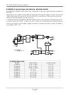
Accessories
72
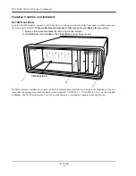
Features, Controls, and Indicators
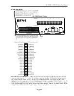
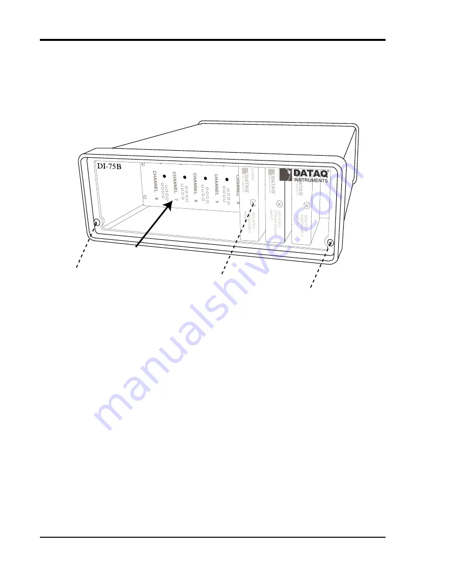
DI-75B Front Panel
Access to the 5B modules is gained by removing the two screws on each side of the front panel, and then removing
the front panel and bezel.
When reattaching the front panel, take care not to overtighten the two screws.
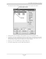
DI-5B modules are installed on (or removed from) a socketed backplane and are secured to the backplane with a non-
removable mounting screw. Each channel position is labeled “CHANNEL 1,” “CHANNEL 2,” etc., on the socketed
backplane. The DI-5B modules can be mixed or matched in any combination suitable for the application.
1. Remove front panel and bezel by removing the two screws.
2. DI-5B Modules are installed to the 5B backplane using the set screw.
5B backplane
1
1
2
Содержание DI-725/E
Страница 2: ......
Страница 4: ......
Страница 6: ......
Страница 10: ......
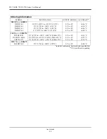
Страница 16: ...DI 720 DI 722 DI 730 Series User Manual Specifications 6 Power DI 720 4 5 Watts DI 722 10 Watts DI 730 14 Watts...
Страница 32: ......
Страница 40: ......
Страница 45: ...DI 720 DI 722 DI 730 Series User Manual Block Diagram 35 6 Block Diagram DI 720 Series 1 32...
Страница 46: ...DI 720 DI 722 DI 730 Series User Manual Block Diagram 36 DI 722 Series...
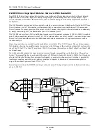
Страница 47: ...DI 720 DI 722 DI 730 Series User Manual Block Diagram 37 DI 730 Series Analog Input I S O L A T I O N...
Страница 106: ......
Страница 107: ......


