DI–720/DI–722/DI–730 Series User Manual
Accessories
47
lead per channel). High-level inputs are typically low impedance, no-conditioning-required signals in the range of
±1.25 to ±10 volts full scale.
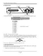
DI-725 Rear Panel
POWER switch
— Controls power to the DI-725 instrument. 1 is on, 0 is off.
POWER input jacks
— Allows you to apply an alternate power source to the instrument, if necessary. The DI-725 is
powered by its host DI-400, DI-720, or DI-730 instrument and in most cases will not need an additional power sup-
ply. However, many factors can influence how much power is available to the DI-725 from its host instrument. When
the DI-725 cannot derive adequate power from its host instrument, the POWER LOW indicator will glow red. This
indicates that an alternate power source is necessary. Any suitable power source (+9 to +36 volts DC at 3A maxi-
mum) may be connected to either jack to provide the necessary power. When an alternate power source is connected,
the remaining jack can be used as an additional power outlet.
POWER status lamp
— Glows green when the POWER switch is in the 1 position, indicating power is applied.
POWER LOW lamp
— Glows red when the DI-725 cannot derive adequate power from its host instrument. In this
case, an alternate power source is required.
If the POWER LOW lamp comes on and you are using the DI-725 with a DI-720 or DI-730, the power supply that is
powering these host instruments can be used to power the DI-725 as well. Simply unplug the five-pin DIN end of the
power adapter cable that is currently supplying power to your DI-720 or DI-730, and plug it into one of the DI-725’s
power input jacks. Now plug one end of the supplied dual-ended power cable into the remaining power jack on the
DI-725 and plug the other end into the host instrument power input jack.
EXPANSION OUT connector
— Used to connect multiple DI-725’s together. Connect one end of an expansion
cable to this connector and connect the other end of the cable to EXPANSION IN on the next DI-725.
Pin 1
EXPANSION OUT is used to connect several DI-725s
together. A total of 240 channels may be configured
using multiple DI-725s. Simply connect one end of the
cable here, and the other end of the cable to
EXPANSION IN on the next DI-725.
Connect the appropriate end of the expansion cable to
the host instrument, then connect the other end of the
cable to EXPANSION IN.
Содержание DI-725/E
Страница 2: ......
Страница 4: ......
Страница 6: ......
Страница 10: ......
Страница 16: ...DI 720 DI 722 DI 730 Series User Manual Specifications 6 Power DI 720 4 5 Watts DI 722 10 Watts DI 730 14 Watts...
Страница 32: ......
Страница 40: ......
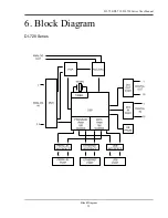
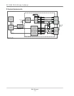
Страница 45: ...DI 720 DI 722 DI 730 Series User Manual Block Diagram 35 6 Block Diagram DI 720 Series 1 32...
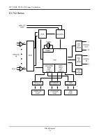
Страница 46: ...DI 720 DI 722 DI 730 Series User Manual Block Diagram 36 DI 722 Series...
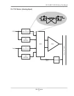
Страница 47: ...DI 720 DI 722 DI 730 Series User Manual Block Diagram 37 DI 730 Series Analog Input I S O L A T I O N...
Страница 106: ......
Страница 107: ......

