
DI–720/DI–722/DI–730 Series User Manual
Accessories
51
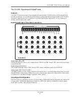
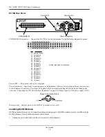
DI-730 Host Instruments
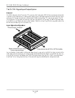
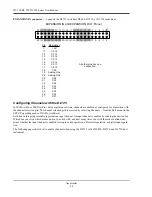
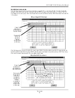
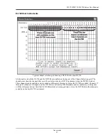
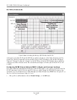
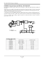
The following channel selection grid is typical when a single DI-725 is used with a DI-730. Note that the DI-730
channels are enabled on the top row of the grid and the DI-725 channels are enabled on the row labeled “MUX A”.
The shaded area on the top row of the grid shows the channels that are still available on the host DI-730 instrument
when the DI-725 is added.
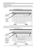
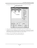
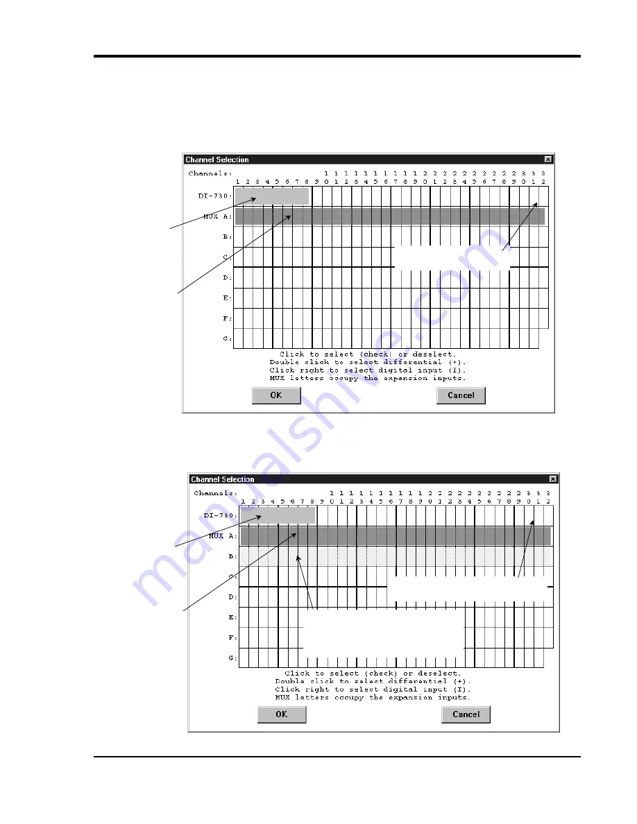
The following grid is typical of two DI-725’ s used with a DI-730. Note the pattern. Each DI-725 consumes the two
highest-numbered channels on the host DI-730, and the expansion channels are enabled on the next MUX row down.
The result is similar when more DI-725’s are added to the system.
When a Single DI-725 is Used.
These 8
channels are
still available on
the host DI-730.
A A
These are the
32 DI-725
expansion
channels
(enable them
on this row).
These 2 channels are
consumed by the DI-725.
When Two DI-725’s are Used.
These 8
channels are
still available on
the host DI-730.
A A
These are the
32 expansion
channels on the
first
DI-725
(the one directly
connected to
the DI-730).
Enable them on
this row.
These 4 channels are consumed by
the DI-725’s.
B B
These are the next 32 expansion
channels on the
second
DI-725 (the
one
not
directly connected to the DI-
730). Enable them on this row.
Содержание DI-725/E
Страница 2: ......
Страница 4: ......
Страница 6: ......
Страница 10: ......
Страница 16: ...DI 720 DI 722 DI 730 Series User Manual Specifications 6 Power DI 720 4 5 Watts DI 722 10 Watts DI 730 14 Watts...
Страница 32: ......
Страница 40: ......
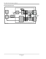
Страница 45: ...DI 720 DI 722 DI 730 Series User Manual Block Diagram 35 6 Block Diagram DI 720 Series 1 32...
Страница 46: ...DI 720 DI 722 DI 730 Series User Manual Block Diagram 36 DI 722 Series...
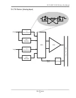
Страница 47: ...DI 720 DI 722 DI 730 Series User Manual Block Diagram 37 DI 730 Series Analog Input I S O L A T I O N...
Страница 106: ......
Страница 107: ......


