

DI–720/DI–722/DI–730 Series User Manual
Accessories
71
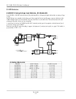
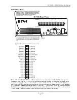
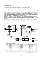
DI-75B 5B Module Channel Expander
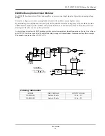
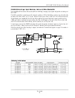
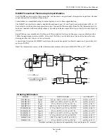
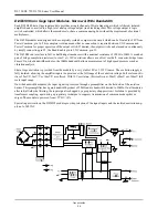
The DI-75B is an eight-channel, 5B-module expansion device for DI-720, DI-722, and DI-730 instruments. Each DI-
75B accepts up to eight high performance, plug-in signal conditioning modules, thereby expanding the measurement
capability of it host instrument to include virtually any isolated, industrial-type signal. Each DI-75B is provided with
the appropriate cable to connect it to its host instrument.
Each DI-75B channel consumes one channel from its host instrument in return for the isolated, signal-conditioned
input it provides. A maximum of two DI-75B instruments may be connected to its host instrument to get a total of 16,
5B-conditioned input channels (in addition to any remaining channels within the host instrument). Signal connections
are made to the DI-75B through a removable screw terminal block. Power is obtained from the host instrument
through the supplied, dual-ended power cable.
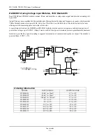
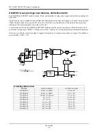
Connecting the DI-75B to the Host Instrument
NOTE: The included expansion signal cable and the dual-ended power cable are sized to fit when the DI-75B is
stacked on top of (or below) the host instrument. If these instruments are not in a stacked configuration, do so before
proceeding.
6.
Connect the appropriate end of the included expansion signal cable to the EXPANSION port on the rear panel of
the host instrument.
7.
Connect the other end of the expansion cable to EXPANSION IN on the rear panel of the DI-75B.
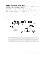
Applying Power to the DI-75B
A separate power supply is not required. Power is obtained from the host instrument through the dual-ended power
cable supplied with the DI-75B. Apply power using the following procedure:
1.
Unplug the five-pin DIN end of the power adapter cable that is currently supplying power to your DI-720, DI-
722, or DI-730, and plug it into one of the DI-75B's power input jacks.
2.
Plug one end of the dual-ended power cable into the remaining power jack on the DI-75B and plug the other end
into the host instrument power input jack.
Содержание DI-725/E
Страница 2: ......
Страница 4: ......
Страница 6: ......
Страница 10: ......
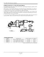
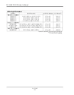
Страница 16: ...DI 720 DI 722 DI 730 Series User Manual Specifications 6 Power DI 720 4 5 Watts DI 722 10 Watts DI 730 14 Watts...
Страница 32: ......
Страница 40: ......
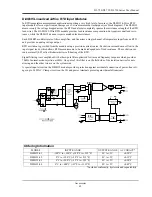
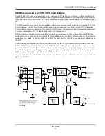
Страница 45: ...DI 720 DI 722 DI 730 Series User Manual Block Diagram 35 6 Block Diagram DI 720 Series 1 32...
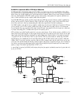
Страница 46: ...DI 720 DI 722 DI 730 Series User Manual Block Diagram 36 DI 722 Series...
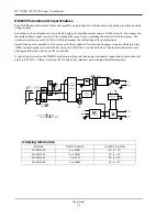
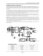
Страница 47: ...DI 720 DI 722 DI 730 Series User Manual Block Diagram 37 DI 730 Series Analog Input I S O L A T I O N...
Страница 106: ......
Страница 107: ......


