DI–720/DI–722/DI–730 Series User Manual
Accessories
56
Enabling CJC for Thermocouple Modules
If you are installing a Thermocouple Input Module (see “DI-8B47 Linearized Thermocouple Input Modules” on
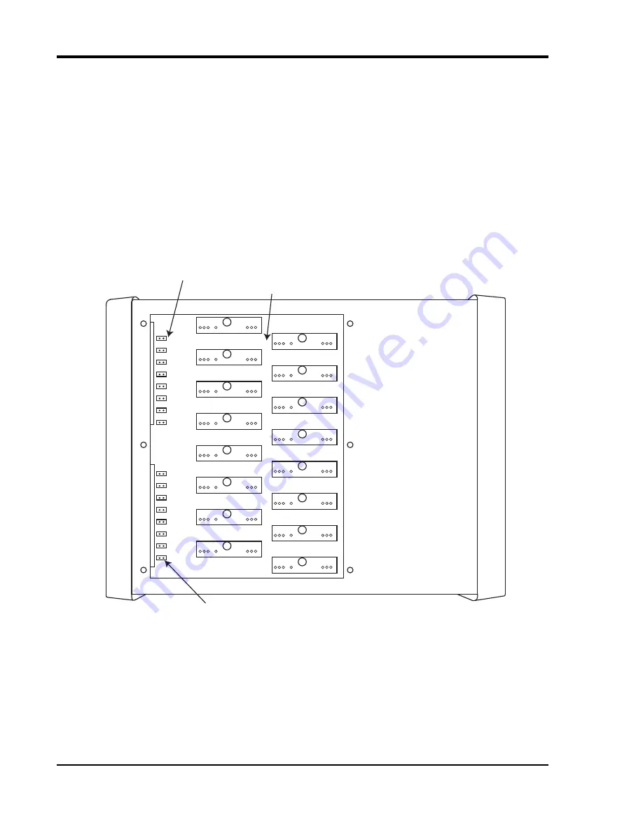
page 69) you must enable the Cold Junction Compensation jumper. Each channel has its own CJC enable jumper
located towards the front of the instrument on the instrument circuit board (see also “Installing DI-8B Modules” on
page 54 for disassembly).
Tip: Install all unused jumpers onto one pin of each channel so they cannot be accidentally
misplaced.
1.
Unplug the device and make sure there is no power to the instrument.
2.
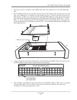
Unscrew the six screws on the top of the instrument and remove the top hatch cover to reveal the DI-8B back-
plane and the CJC Enable Jumpers.
3.
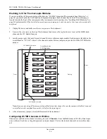
Install a jumper onto the board for each channel that uses a thermocouple module. Each jumper is labelled on the
circuit board as “TC CH#” where # is the channel number. Sixteen jumpers are provided with the DI-78B for this
purpose.
Note: If you are not using a Thermocouple Input Module on that channel be sure the jumper is disabled (removed
or installed on only one pin) because this will affect the input signal.
4.
After all necessary jumpers are installed reassemble the instrument.
Configuring DI-78B Channels in W
IN
D
AQ
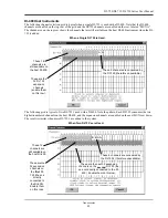
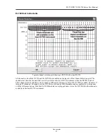
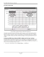
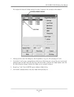
Channels are enabled in the channel selection grid (select
Channels...
from the
Edit
menu) in W
IN
D
AQ
Data Acqui-
sition software. Each box in the grid represents an input channel. Click on the desired channel box to enable a chan-
nel.
CHANNEL 1
CHANNEL 2
CHANNEL 3
CHANNEL 4
CHANNEL 5
CHANNEL 6
CHANNEL 7
CHANNEL 8
CHANNEL 9
CHANNEL 10
CHANNEL 11
CHANNEL 12
CHANNEL 13
CHANNEL 14
CHANNEL 15
CHANNEL 16
TC CH1
TC CH8
TC CH7
TC CH6
TC CH5
TC CH4
TC CH3
TC CH2
TC CH9
TC CH16
TC CH15
TC CH14
TC CH13
TC CH12
TC CH11
TC CH10
CJC Enable Jumpers
Circuit Board with
DI-8B Backplane
Front
CJC Enable Jumpers
Casing
Rear
Содержание DI-725/E
Страница 2: ......
Страница 4: ......
Страница 6: ......
Страница 10: ......
Страница 16: ...DI 720 DI 722 DI 730 Series User Manual Specifications 6 Power DI 720 4 5 Watts DI 722 10 Watts DI 730 14 Watts...
Страница 32: ......
Страница 40: ......
Страница 45: ...DI 720 DI 722 DI 730 Series User Manual Block Diagram 35 6 Block Diagram DI 720 Series 1 32...
Страница 46: ...DI 720 DI 722 DI 730 Series User Manual Block Diagram 36 DI 722 Series...
Страница 47: ...DI 720 DI 722 DI 730 Series User Manual Block Diagram 37 DI 730 Series Analog Input I S O L A T I O N...
Страница 106: ......
Страница 107: ......

