vi
DS41
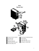
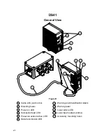
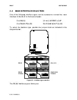
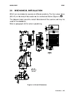
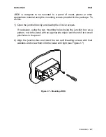
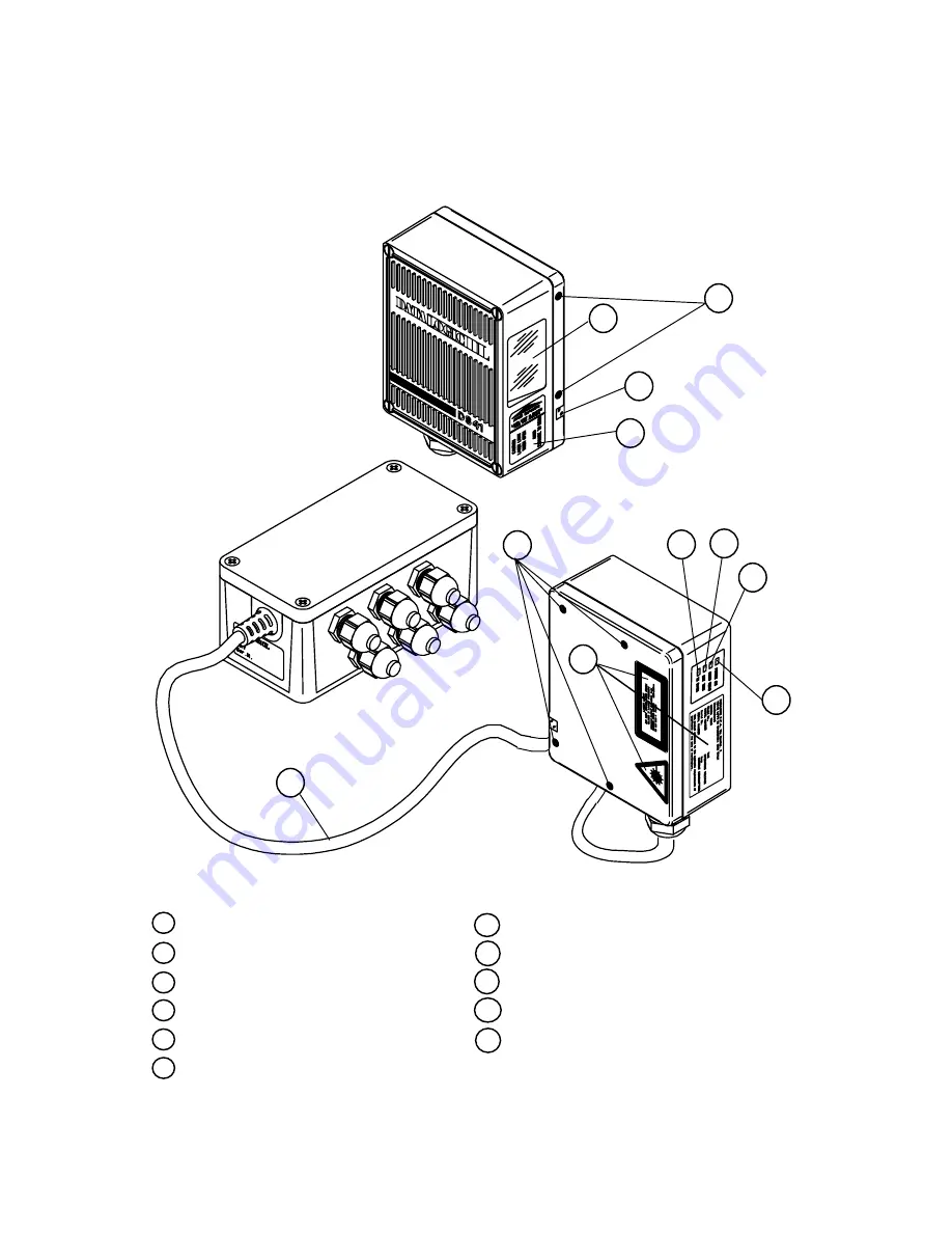
General View
11
10
9
8
2
1
7
6
5
4
3
Figure B
6
Data transmission LED
Cable with junction box
1
Mounting holes
2
Successful read LED
4
Presence sensor active LED
5
Power on LED
3
Laser active LED
9
8
Warning label
Laser beam output window
10
7
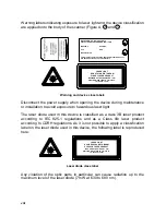
Warning and Classification labels
11 Accessory mounting holes
Содержание DS41-X0
Страница 1: ...DS41 Installation Manual ...
Страница 2: ...DS41 INSTALLATION MANUAL ...
Страница 11: ...x This page is intentionally left blank ...
Страница 51: ...DS41 DATALOGIC 4 2 Maintenance This page is intentionally left blank ...


