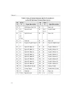
Wiring Signals
55
5
5
5
5
5
5
5
5
5
25
22
Analog In 20
26
56
Analog In 28/
Analog Input 20 Return
27
21
Analog In 21
28
55
Analog In 29/
Analog Input 21 Return
29
20
Analog In 22
30
54
Analog In 30/
Analog Input 22 Return
31
19
Analog In 23
32
53
Analog In 31/
Analog Input 23 Return
33
18
Amp Low
34
49
Analog Ground
35
11
+15 V Output
36
45
Power Ground
37
12
−
15 V Output
38
46
A/D Trigger Output
39
15
Analog Trigger
40
52
Analog Ground
41
17
Analog Output 0+
42
51
Analog Output Ground
43
16
Analog Output 1+
44
50
+5 Volts_Ref Output
45
10
External D/A TTL
Trigger
46
44
External D/A Clock
Input
47
47
A/D Sample Clock
Output
48
13
External A/D Sample
Clock Input
49
14
External A/D TTL
Trigger
50
48
External A/D Trigger
and Clock Enable
51
35
Digital Ground
52
1
+5 V Output
53
39
Digital Ground
54
5
User Clock Input 0
55
3
User Counter
Output 0
56
37
External Gate 0
Table 4: Screw Terminal Assignments on the STP268 for
Connector J1 on the DT3010-268 (cont.)
TB #
J1
Pin #
Signal Description
TB #
J1
Pin #
Signal Description
Содержание DT3010 Series
Страница 1: ...R DT3010 Series UM 16868 C Getting Started Manual ...
Страница 11: ...1 1 Overview DT3010 Series Key Hardware Features 2 DT3010 Series Software 3 Getting Started Procedure 4 ...
Страница 22: ...Chapter 2 12 ...
Страница 36: ...Chapter 3 26 ...
Страница 114: ...Chapter 5 104 ...
Страница 136: ...Appendix A 126 ...
Страница 142: ...Index 132 ...


