Chapter 5
72
Note that since they measure the difference between the signals at the
high (+) and low (
−
) inputs, differential connections usually cancel
any common-mode voltages, leaving only the signal. However, if you
are using a grounded signal source and ground loop problems arise,
connect the differential signals to the DT740 or STP268 screw
terminal panel as shown in
, or to the STP268-EC as shown
in
.
Make sure that the low side of the signal (
−
) is connected to ground at
the signal source, not at the screw terminal panel, and do not tie the
two grounds together.
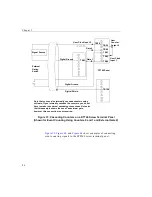
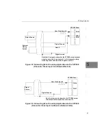
Figure 21: Connecting Differential Voltage Inputs from a Grounded Signal
Source to the DT740 or STP268 (Shown for Channel 0)
Grounded
Signal
Source
+
−
TB1
TB2
Analog In 0
Analog In 0
Return
E
s
Signal Source
Ground V
g1
DT740 or STP268 Panel
Resistor R1 should be installed for bias return
in case the external ground is floating.
TB34
Analog Ground
R1
Note that the signals shown for the STP268
screw terminal panel correspond to connector
J1.
Содержание DT3010 Series
Страница 1: ...R DT3010 Series UM 16868 C Getting Started Manual ...
Страница 11: ...1 1 Overview DT3010 Series Key Hardware Features 2 DT3010 Series Software 3 Getting Started Procedure 4 ...
Страница 22: ...Chapter 2 12 ...
Страница 36: ...Chapter 3 26 ...
Страница 114: ...Chapter 5 104 ...
Страница 136: ...Appendix A 126 ...
Страница 142: ...Index 132 ...


