Wiring Signals
61
5
5
5
5
5
5
5
5
5
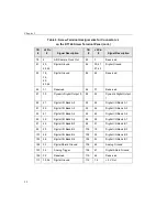
lists the screw terminal assignments for connector J2 on the
STP268-EC screw terminal panel.
lists the screw terminal assignments for connector J3 on the
STP268-EC screw terminal panel.
Table 7: Screw Terminal Assignments for Connector J2 on the STP268-EC
TB
#
J2 Pin
#
Signal Description
TB
#
J2 Pin
#
Signal Description
6
41
Digital I/O 3
7
43
Digital I/O 2
8
45
Digital I/O 1
9
47
Digital I/O 0
40
33
Digital I/O 7
41
35
Digital I/O 6
42
37
Digital I/O 5
43
39
Digital I/O 4
Table 8: Screw Terminal Assignments for Connector J3 on the STP268-EC
TB
#
J3 Pin
#
SIgnal Description
TB
#
J3 Pin
#
Signal Description
16
22
DAC1_OUT
a
17
20
DAC0_OUT
b
18
25
Amp Low
−
26
Not Connected
27
23
Analog Input 07
28
19
Analog Input 06
29
17
Analog Input 05
30
13
Analog Input 04
31
11
Analog Input 03
32
7
Analog Input 02
33
5
Analog Input 01
34
1
Analog Input 00
51
21, 24
Analog Ground
c
52
3, 6, 9,
12, 15,
18, 21,
24
Analog Ground
Содержание DT3010 Series
Страница 1: ...R DT3010 Series UM 16868 C Getting Started Manual ...
Страница 11: ...1 1 Overview DT3010 Series Key Hardware Features 2 DT3010 Series Software 3 Getting Started Procedure 4 ...
Страница 22: ...Chapter 2 12 ...
Страница 36: ...Chapter 3 26 ...
Страница 114: ...Chapter 5 104 ...
Страница 136: ...Appendix A 126 ...
Страница 142: ...Index 132 ...


