Chapter 4
40
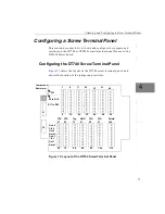
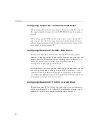
Configuring Jumper W1 - Common Ground Sense
When shipped from the factory, jumper W1 connects the low side of
the input amplifier (Amp Low) on the DT3010-268 board to analog
ground.
When using pseudo-differential analog inputs, remove jumper W1
and connect Amp Low to a remote common-mode voltage to reject
offset voltages common to all 32 input channels. Refer to
for
an example of using jumper W1.
Configuring Resistors R1 to R16 - Bias Return
Resistor locations R1 to R16 connect the low side of analog input
channels to analog ground. These resistor locations are typically used
when connecting differential inputs to analog input channels 0 to 15,
where R1 corresponds to analog input channel 0, and R16
corresponds to analog input channel 15.
The high side of the corresponding analog input channels returns the
source input impedance through the bias return resistors to the low
side of the channels, then to analog ground. Typical resistor values
are 1 k
Ω
to 100 k
Ω
depending on the application. Refer to
for
an example of using bias return resistors.
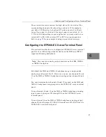
Configuring Resistors R17 to R32 - Current Shunt
Resistor locations R17 to R32 are typically used to convert current to
voltage on channels 0 to 15, where R17 corresponds to analog input
channel 0, and R32 corresponds to analog input channel 15.
Содержание DT3010 Series
Страница 1: ...R DT3010 Series UM 16868 C Getting Started Manual ...
Страница 11: ...1 1 Overview DT3010 Series Key Hardware Features 2 DT3010 Series Software 3 Getting Started Procedure 4 ...
Страница 22: ...Chapter 2 12 ...
Страница 36: ...Chapter 3 26 ...
Страница 114: ...Chapter 5 104 ...
Страница 136: ...Appendix A 126 ...
Страница 142: ...Index 132 ...


