Wiring Signals
49
5
5
5
5
5
5
5
5
5
Note:
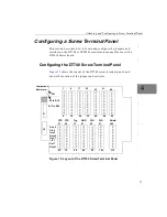
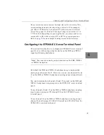
If you are connecting a high-speed clock to the DT740, it is
recommended that you connect the return to the adjacent ground
screw terminal.
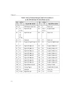
lists the screw terminal assignments for connector J1 on the
DT740 screw terminal panel;
lists the screw terminal
assignments for connector J2 on the DT740 screw terminal panel.
Table 2: Screw Terminal Assignments for Connector J1
on the DT740 Screw Terminal Panel
TB
#
J1 Pin
#
Signal Description
TB
#
J1 Pin
#
Signal Description
1
25
Analog Input 00
2
50
Analog Input 08/
Analog Input 00 Return
3
24
Analog Input 01
4
49
Analog Input 09/
Analog Input 01 Return
5
23
Analog Input 02
6
48
Analog Input 10/
Analog Input 02 Return
7
22
Analog Input 03
8
47
Analog Input 11/
Analog Input 03 Return
9
21
Analog Input 04
10
46
Analog Input 12/
Analog Input 04 Return
11
20
Analog Input 05
12
45
Analog Input 13/
Analog Input 05 Return
13
19
Analog Input 06
14
44
Analog Input 14/
Analog Input 06 Return
15
18
Analog Input 07
16
43
Analog Input 15/
Analog Input 07 Return
Содержание DT3010 Series
Страница 1: ...R DT3010 Series UM 16868 C Getting Started Manual ...
Страница 11: ...1 1 Overview DT3010 Series Key Hardware Features 2 DT3010 Series Software 3 Getting Started Procedure 4 ...
Страница 22: ...Chapter 2 12 ...
Страница 36: ...Chapter 3 26 ...
Страница 114: ...Chapter 5 104 ...
Страница 136: ...Appendix A 126 ...
Страница 142: ...Index 132 ...


