Chapter 5
100
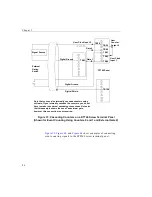
Figure 52: Cascading Counters for the STP268
(Shown for One-Shot Using Counters 0 and 1 and External Gate 1)
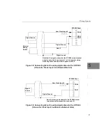
, and
show examples of connecting
pulse output applications to the STP268-EC screw terminal panel.
Other combinations of signals can be used.
TB54
Signal Source
Digital Ground
User Clock Input 0
TB57
TB60
Digital Ground
Gate 1
One-Shot
Trigger
TB55
TB58
User
Counter
Output 0
User Clock
Input 1
TB53
Note that the signals shown for the STP268 screw
terminal panel correspond to connector J1.
STP268 Panel
Содержание DT3010 Series
Страница 1: ...R DT3010 Series UM 16868 C Getting Started Manual ...
Страница 11: ...1 1 Overview DT3010 Series Key Hardware Features 2 DT3010 Series Software 3 Getting Started Procedure 4 ...
Страница 22: ...Chapter 2 12 ...
Страница 36: ...Chapter 3 26 ...
Страница 114: ...Chapter 5 104 ...
Страница 136: ...Appendix A 126 ...
Страница 142: ...Index 132 ...


