


Data Industrial Series 340 Btu transmitter Owner’s Manual
4
Temp
2
Temp
1
Mat
10K Thermistors
NOTE:
maximum sinking current
is 100 mA @ 36 VDC.
Pulse Input
Device
(-)
(+)
Po
w
er I
AC L/DC
+
AC C/DC
Ou
tp
ut
Pulse Out
-
Pulse Out
+
Output LED
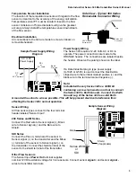
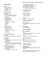
Temperature Element Wiring
The Data Industrial thermistors are not polarity sensitive.
Connect thermistor closest to the flow sensor to Series 340
terminal block marked TEMP 1 and the other thermistor
wires to Series 340 terminal marked TEMP 2.
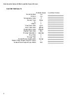
Pulse Output Wiring
The Series 340 has solid state switch output rated for a
maximum sinking current of 100 mA @ 36 VDC. In most
cases the pulse out (+) terminal of the 340 will connect to
the Input pulse (+) and the pulse out (-) terminal to the Input
pulse (-) of the receiving device. These terminals are located
on a separate two terminal removable header on the 340
labeled “Output”. Observe the electrical polarity of the
output.
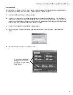
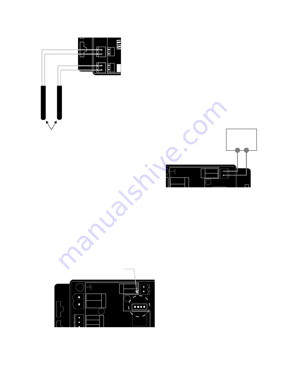
Communications cable wiring
Field calibration requires a Data Industrial A340 Programming kit (consisting of a custom cable and
software) and a PC running Windows
®
9x, ME, NT or 2000. In order to calibrate, the Series 340 must
be connected to power, and the A301 cable must be connected to the 340 Comm port connector and an
available 9-pin COM port on a computer.
Note:
The Data Industrial A301 Cable will work
with all 300 Series products. However
the older version of the cable (A300)
does not have sufficient bandwidth to
work with the Series 340 Transmitters.
Data Industrial provides free programming
software updates via the Internet for all of
Series 300 devices. Go to
www.dataindustrial.com for these updates.
Sample Pulse Output wiring
Diagram
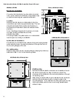
Thermistor Wiring Diagram
Location of the
DIC Communication Port
DIC Comm Port
(Plug in A301 Program Cable here to program)
Se
ns
or
In
Power Out
Signal
+
Signal
-
Po
w
er I
n
AC L/DC
+
AC C/DC
-
Ou
tp
ut
Pulse Out
-
Pulse Out
+
Output LED
Model: 340
Input LED
D.
I.C
.
Co
m
m
Po
rt


