


Data Industrial Series 340 Btu transmitter Owner’s Manual
7
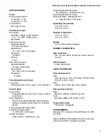
SPECIFICATIONS
Power
Power supply options:
12-35 VDC +/- 5%
12-24 VAC +/- 10%
Current Draw:
60 mA @ 12 VDC
Flow Sensor Input
All sensors:
Excitation voltage 3 wire sensors:
7.9 – 11.4 VDC 270
Ω
source
impedance
Pulse type sensors:
Signal amplitude:
2.5 VDC threshold
Signal limits:
Vin < 35V (DC or AC peak)
Frequency:
0-10kHz
Pull-up:
2 k
Ω
Sine Wave Sensors:
Signal amplitude:
10 mV p-p threshold
Signal limits:
Vin < 35V (DC or AC peak)
Frequency:
0-10kHz
Temperature Sensor Input
2 required:
10 k
Ω
thermistor, 2 wire, type II, 10 k
Ω
@ 25°C
Pulse Output
Pulse Width:
Programmable from 50 mS to 5 Sec in 50mS
increments
Pulse frequency:
Max of 10Hz @ 50mS pulse width program-
mable to scaling requirements of connected
device
Opto-isolated solid state switch
Operating Voltage range:
0 - ±60V (DC or AC peak)
Closed (on) state:
Load Current - 700mA max. over
operating temperature range
On-resistance - 700m
Ω
max. over
operating temperature range
Open (off) state – leakage @ 70°C
<1 A @ 60V (DC or AC peak)
Operating Temperature
-29° C to +70° C
-20° F to +158° F
Storage Temperature
-40° C to +85° C
-40° F to +185° F
Weight
4.8 oz. With headers installed
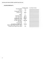
SENSOR CALIBRATION
Data Industrial
Use “K” and “offset” provided in sensor owner’s
manual
Other Sensors
Check with factory
UNITS OF MEASURE
Flow measurement
Rate:
gpm, gph, l/sec, l/min, l/hr, ft3/sec, ft3/min, ft3/hr,
m3/sec, m3/min, m3/hr
Total:
gallons, liters, cubic feet, cubic meters
Energy measurement
Rate
kBtu/min, kBtu/hr, kW, MW, hp, tons
Total
Btu, kBtu, MBtu, kWh, MWh, kJ, MJ
Temperature Units
Fahrenheit, Centigrade
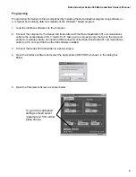
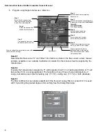
PROGRAMMING
Requires PC or laptop running Windows
9x, ME,
NT, 2000
Data Industrial A-340 programming kit containing
software and A301 programming cable