47
0
3
9
7
5
4
•
V
e
rsi
o
n
2
.0
•
0
8
.0
3
.2
0
1
1
EN
EN
EN
EN
EN
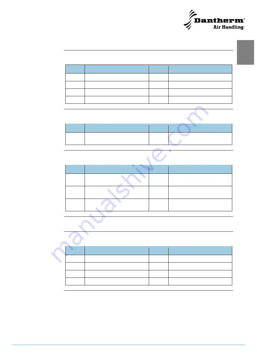
Wiring diagram
continued
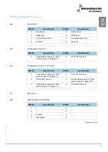
J4
Fan control:
PIN No.
Specification
PIN No.
Specification
1
Tacho fan 1
5
Tacho fan 2
2
PWM fan 1
6
PWM fan 2
3
10V reference fan 1
7
10V reference fan 2
4
0V fan 1
8
0V fan 2
J5
Temperature sensor T1
PIN No.
Specification
PIN No.
Specification
1
Temperature sensor T1: NTC
sensor input 2,7
Ω @ 25 ºC
2
0V for NTC sensor
J6
Temperature sensor T2, T3 og T4:
PIN No.
Specification
PIN No.
Specification
1
Temperature sensor T2: NTC
sensor input 2,7
Ω @ 25 ºC
4
0V for NTC sensor
2
0V for NTC sensor
5
Temperature sensor T4: NTC
sensor input 2,7
Ω @ 25 ºC
3
Temperature sensor T3: NTC
sensor input 2,7
Ω @ 25 ºC
6
0V for NTC sensor
J7
Not in use
J8
Input for option (humidistat):
PIN No.
Specification
PIN No.
Specification
1
-
5
-
2
-
6
-
3
12 VDC
7
-
4
Humidistat
8
-
Continued overleaf
Содержание HRV 5
Страница 1: ...Focus Trust Initiative HRV 5 Service manual DA GB DE No 039994 rev 2 0 08 03 2011...
Страница 2: ...2005 layout...
Страница 3: ...HRV 5 Service manual EN DA DE No 039994 rev 2 0 08 03 2011...
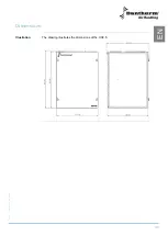
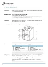
Страница 47: ...45 039754 Version 2 0 08 03 2011 EN Dimensions Illustration The drawing illustrates the dimensions of the HRV 5...
Страница 54: ...52...
Страница 97: ...45 039753 Version 2 0 08 03 2011 DA Dimensioner Illustration Illustrationen viser dimensionerne p en HRV 5...
Страница 104: ...52...
Страница 138: ...36 Fortsetzung auf der n chsten Seite...
Страница 148: ...46 Abmessungen Abbildung Die Abbildung zeigt die Abmessungen eines HRV 5...
Страница 154: ...52 Firmenstempel Datum und Unterschrift...
Страница 157: ...2005 layout...

