background image


21 

070719 

 Ve

rs

io

1

.1

 • 

0

5

.1

0

.2

0

1

2


EN


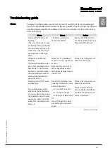
Troubleshooting guide 


Alarms 

For easier troubleshooting, use the remote control on which all alarms are displayed. 
See the Functional Description section in the user guide for how to activate the different 
operating modes. Identify the problem in the left-hand column and follow the instruc-
tions on the right: 


Alarm 

Cause 

Action 

Yellow LED (30/min) and 
beeping. 
(The unit continues to oper-
ate but electricity consump-
tion and noise levels are in-
creased as a result of high 
pressure loss in the dirty 
filter). 

The filters need to be 
checked/replaced. 

Replace the filters and re-
set the unit filter timer. See 
Preventive Maintenance 

Constant, red LED and 
beeping. 
The unit continues to oper-
ate in fail-safe mode (Fail 
Safe Mode 1), which corre-
sponds to standard opera-
tion, but without access to 
cooling function with by-
pass (not HCV 4). 

Defect on T1 outside air 
sensor or on T2 supply air 
sensor. 
Note that the unit in fail-
safe mode always keeps 
the bypass damper closed 
(not HCV 4). 

Check and, if required, re-
place the sensor set. 

Flashing red LED (30/min) 
and beeping. 
 
The unit operates in fail-
safe mode (Fail Safe Mode 
2), during which the supply 
fan operates only at lowest 
speed (Fan Step 1) and the 
extract fan operates at Fan 
Step 1/2. 

One of the following com-
ponents is defective or has 
a bad connection: 


T3 extract air sensor 


T4 exhaust sensor 


The built-in RH sensor 

Or: 
One of the two fans does 
not achieve the required 
speed 

Check and, if required, re-
place the sensor set. 


Check that the fans are 
able to rotate unhindered 
and that the cables are se-
curely connected. 

Continued overleaf 

Содержание HCV 5

Страница 1: ...HCV 4 HCV 5 Installation manual Rev 1 1 EN DA DE FR ...

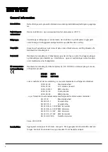
Страница 2: ...hold for trykfejl og ændringer Dantherm can accept no responsibility for possible errors and changes Irrtümer und Änderungen vorbehalten Dantherm n assume aucune responsabilité pour erreurs et modifications éventuelles ...

Страница 3: ...gher The ducts must be covered and the unit must not be connected until the house is ready for occupation which means that the house is clean and dry This is to prevent building dust and condensation from settling in the duct system and to prevent hygiene prob lems in the ventilation unit at a later date If the above is not complied with the warranty on the unit will lapse and any type of service ...

Страница 4: ...ion of Conformity Dantherm Air Handling A S Marienlystvej 65 DK 7800 Skive declares at its own liability that the following product 352425 HCV 4 352422 HCV 5v12 covered by this declaration complies with the following directives 2006 42 EC Machine Safety 2006 95 EC LVC Directive low voltage 2004 108 EC EMC Directive 2002 95 EC RoHS Directive 2002 96 EC WEEE direktiv and is manufactured in complianc...

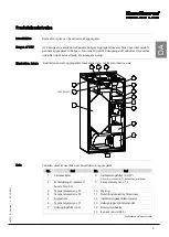
Страница 5: ...tion shows the different parts of the unit seen from within Parts The table lists the main parts in the unit No Part No Part 1 Heat exchanger 8 Air supply filter G4 F7 G4 filter is standard F7 pollen filter is an op tional extra 2 Electrical connections located at the bottom of the HCV 5 9 Temperature sensor T4 3 Temperature sensor T2 10 Controls 4 Temperature sensor T3 11 Reset button for filter ...

Страница 6: ...heated by the extract air from the house T2 Supply air The supply air is heated by means of heat recovery from the extract air T3 Extract air Polluted and warm extract air is used to heat up the outside air by means of heat recovery in the heat ex changer T4 Exhaust air The heat of the extract air is used to heat the cold out side air The exhaust air is led out of the house T2 T3 T4 T1 ...

Страница 7: ...ion cap screws Ducts The ducts connected to the unit must have at least the same diameter as the unit s duct connection or larger Dimensions can be seen in the technical data section Dimensions of ducts and sound absorbers must be in conformity with national stand ards and guidelines in the current building legislation Contact your Dantherm dealer for further advice Noise and vibrations from the u...

Страница 8: ...ws must have a breaking strength of at least 365 N NOTE Please note that Dantherm Air Handling is able to provide spe cial fixtures to reduce the depth of the unit if the HCV 4 needs to be built into a cabinet with a door 2 Mount the two spacers on the back of the unit as shown 3 Lift the unit onto the mounting rail Due to the weight of the unit two people are required to lift it into place 4 Conn...

Страница 9: ...onnections using NPU nip ple and insulated flexible ducts Flexi ble ducts must be fully stretched and without kinks to avoid unnecessary loss of pressure Connection Outside air T1 Supply air T2 Extract air T3 Exhaust air T4 8 The whole duct system should be insulated with a minimum of 100 mm insu lation Place the ducts e g under a minimum of 100 mm ceiling insulation If insulation is used around t...

Страница 10: ... the ceiling with a gradient away from the ventilation system The purpose is to prevent any drifting snow driving rain or condensation running down into and damaging the ventilation system installa tion and house The warranty does not cover damage to the unit building parts or insulation caused by accumulated snow water in the ducts Optional extras To install optional extras from Dantherm Air Hand...

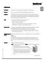
Страница 11: ...rer s supplier s recommendations before an initial adjustment of the HCV is commenced Ensure that you have the following at hand before you start the installation Pressure manometer with approx 5 mm pipes matching the pressure connections on the unit which are 6 mm Initial adjustment of air flow When the initial adjustment is carried out it is important to ensure that the air flows are the same Im...

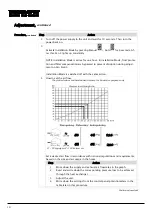
Страница 12: ...ed off with the same action 4 How to set the air flow Set a desired air flow in accordance with national regulations and requirements based on the size and air usage in the house Step Action 1 Write down the supply and exhaust air flow rates in the graph 2 Read and write down the corresponding pressure loss to be achieved through the heat exchanger 3 Adjust the unit 4 Write down the settings from ...

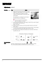
Страница 13: ... adjusting the potentiometer for the supply air fan until the required pres sure difference has been achieved The potentiometer can be found on the con trol panel After adjusting the potentiometers wait approx 2 minutes until the unit is stable again Strong wind against the building may affect the adjustment of the unit 7 Connect the pressure manometer to the pressure pipes P3 and P4 and measure t...

Страница 14: ...on the supply air side as this may have changed after adjustment of the exhaust air Adjust if necessary 10 Adjust the valves in all rooms until the required air flow for each room has been achieved 11 Check the main air flows according to the instructions earlier in this procedure as major valve adjustment may greatly affect the main air flow 12 Write down the final settings for potentiometers air...

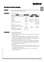
Страница 15: ...ion of exchanger The controls have a built in protection function against preventing ice building up in the heat exchanger If the exhaust air temperature falls below 2 C for more than 1 hours the unit starts to reduce the flow rate of supply air i e RPM on the supply fan are reduced until the exhaust air temperature reaches a minimum of 2 C Frost protection usu ally starts when the outdoor air T1 ...

Страница 16: ...bed in the section on trou bleshooting Service intervals The table provides an overview of service intervals for different parts Service interval Task To be carried out by 0 5 years Filter check Change if required User External cleaning User 1 year Filter replacement User External discharge Certified engineer 2 years Heat exchanger Certified engineer Fans Certified engineer Drip tray internal disc...

Страница 17: ...s Drip tray Ensure that the condensate drain is not blocked in the drip tray and clean the drip tray with soapy water and a brush or cloth every other year to ensure good hygiene inside the unit Internal cleaning Keep the unit clean to ensure seamless operation and good hygiene Internal cleaning should only be carried out if the unit is to be opened anyway e g for other service Check the unit s in...

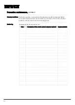
Страница 18: ...mented preventive maintenance Mainte nance must have been carried out at intervals of a minimum of six months The docu mentation must be in the form of a written log journal Service log Complete the log at every service visit Date Description of the service carried out parts replaced Engineer initials ...

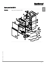
Страница 19: ...17 070719 Version 1 1 05 10 2012 EN Spare parts list HCV 4 Illustration Spare parts list illustration HCV 4 ...

Страница 20: ... 070765 Counterflow cable with plug 1600 mm 10 062045 Power cable with plug 1150 mm P1150 11 062046 Counterflow cable with plug 1150 mm MC1150 12 062023 Rail for drip tray 475x50 mm 13 062063 Supply cable 230 V AC 14 062059 HCP4 control panel 15 063367 Front cover bottom 16 063366 Front cover top 17 062066 Magnet 64x10 mm 18 062018 Polystyrene front complete 19 062694 Filter cover 20 070775 Heat e...

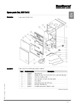
Страница 21: ... numbers Item Product number Description 1 063680 Mounting rail 3 062031 Damper motor 230 V AC 2 Nm 75 sec with split bushing 4 062064 Filter reset button FRB 5 062028 Fan diameter 190 mm 650 mm cable 6 062294 Print MPCB 7 062062 Connection panel CP IEC plug 8 062033 Cabling complete set 9 062047 Temperature sensor cable set wall Continued overleaf ...

Страница 22: ...2046 Counterflow cable with plug 1150 mm MC1150 14 062063 Supply cable 230 V AC 15 062059 HCP4 control panel 16 062057 Rail for drip tray 539x50 mm 17 063369 Front cover bottom 18 062066 Magnet 64x10 mm 19 063368 Front cover top 20 062065 Pressure tube connection for pressure measure ment 21 062029 Filter cover 22 062027 Polystyrene front complete 23 063084 Exchanger 400 mm with insulation 24 0644...

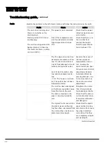
Страница 23: ...tinues to oper ate in fail safe mode Fail Safe Mode 1 which corre sponds to standard opera tion but without access to cooling function with by pass not HCV 4 Defect on T1 outside air sensor or on T2 supply air sensor Note that the unit in fail safe mode always keeps the bypass damper closed not HCV 4 Check and if required re place the sensor set Flashing red LED 30 min and beeping The unit operate...

Страница 24: ...of duct insulation Very low outside temperature be low 10 C The house is not heat ed The system has not been adjusted correctly Examine the cause of the low supply air temperature and cor rect Insulate the ducts Install pre heat Carry out correct initial adjustment Activate Installation Mode by pressing Manual Au to for 6 seconds See the section on initial adjustment The unit has been misaligned s...

Страница 25: ...hat they are not blocked Adjust airflow see the sec tion on how to adjust the unit The unit has not been ad justed correctly The unit is not cooling suf ficiently The unit is an HCV 4 which has no built in bypass module The unit is functioning cor rectly The outside air may be heat ed up before entering the house If required move the inlet grille to the north side of the house The temperatures are...

Страница 26: ...statutory rate required for the house as this may result in the risk of damage from damp and reduced air quality The house is becoming un necessarily dry The unit may be running with too high a level of air replacement for the size and use of the house Check that the unit s air flow is appropriate to the size and use of the house by checking the unit s air flow according to the initial adjustment ...

Страница 27: ... in critical areas Set the unit to Automatic Mode to keep dampness at an appropriate level auto matically Do not let the unit operate constantly at Fan Step 1 or 2 in Manual Mode as it will not guarantee keeping the humidity levels down when the moisture load in the house is high The unit is constantly run ning at the same speed The unit is set to Manual Mode at one fixed speed Set the unit to Aut...

Страница 28: ...nce Dantherm Air Handling A S offers to carry out preventive maintenance on units to en sure that they operate satisfactorily Repairs and call outs In the event of faults on the unit Dantherm Air Handling A S offers a unit repair service An agreement on response times and prices is entered into between the customer and Dantherm Air Handling A S Setup Dantherm Air Handling A S has established a net...

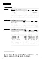
Страница 29: ...erating temperature range with pre heat C 30 to 50 Cabinet data The table below shows the cabinet s technical data Specification Unit HCV 4 HCV 5 Height mm 1005 1055 Width mm 530 590 Depth standard mounting rail rail for plan mounting mm 434 419 584 569 Duct connection mm 125 160 Weight unit kg 32 45 Weight incl packaging kg 42 57 Dimensions incl packaging HxWxD mm H 568 W 1067 D 460 H 606 W 1109 ...

Страница 30: ... 5 63 Hz supply extract Lw dB A 34 35 36 37 37 38 38 39 125 Hz supply extract Lw dB A 40 38 42 40 42 41 44 43 250 Hz supply extract Lw dB A 43 40 45 43 53 50 55 52 500 Hz supply extract Lw dB A 44 44 47 47 42 42 45 45 1000 Hz supply extract Lw dB A 36 41 38 43 41 36 43 38 2000 Hz supply extract Lw dB A 27 33 29 33 39 34 40 35 4000 Hz supply extract Lw dB A 19 24 21 26 27 20 29 22 Sound power suppl...

Страница 31: ...29 070719 Version 1 1 05 10 2012 EN Dimensions HCV 4 Unit dimensions The illustration shows the dimensions on an HCV 4 ...

Страница 32: ...30 Dimensions HCV 5v12 Unit dimensions The illustration shows the dimensions on an HCV 5v12 ...

Страница 33: ...31 070719 Version 1 1 05 10 2012 EN Electrical diagram Diagram This is the electrical diagram for HCV 4 HCV 5v12 ...

Страница 34: ...15 humidity sensor 3 IEC plug 7 initial adjustment of air flow 9 installation 5 mounting rail 5 national legislation 9 noise 23 nominal air flow 9 outside air 4 power cable set 5 pressure loss 11 pressure manometer 9 preventive maintenance 14 recommended approach 14 red LED 21 repairs and call outs 26 reservations 2 reset button for filter timer 3 sensors 13 serial number 1 service agreement 26 se...

Страница 35: ...er på 10 eller højere Kanalerne skal være blændet af og aggregatet må ikke tilsluttes før huset er indflyt ningsklar hvilket vil sige rengjort og udtørret Dette er for at forhindre at byggestøv og kondensvand aflejres i kanalsystemet og ventilationsaggregatet med risiko for hygiej negener på et senere tidspunkt Hvis ikke dette overholdes bortfalder garantien på aggregatet og enhver form for ser vi...

Страница 36: ...elelse eller forpligtelser EU overensstem melseserklæring Dantherm Air Handling A S Marienlystvej 65 DK 7800 Skive erklærer på eget ansvar at følgende produkt 352425 HCV 4 352422 HCV 5v12 som er omfattet af denne erklæring er i overensstemmelse med følgende direktiver 2006 42 EC Maskinsikkerhed 2006 95 EC LVC direktiv lavvolt 2004 108 EC EMC direktiv 2002 95 EC RoHS direktiv 2002 96 EC WEEE direkt...

Страница 37: ...trationen viser aggregatets forskellige dele set fra den interne side Dele Tabellen giver et overblik over hoveddelene i aggregatet Nr Del Nr Del 1 Varmeveksler 8 Indblæsningsfilter G4 F7 G4 filter er standard F7 pollenfilter er tilbehør 2 El tilslutninger placeret i bund af HCV 5 9 Temperatursensor T4 3 Temperatursensor T2 10 Styring 4 Temperatursensor T3 11 Nulstillingsknap for filtertimer 5 Fug...

Страница 38: ...dsugningsluften fra huset T2 Indblæsningsluft Indblæsningsluften er varmet op ved hjælp af varme genvinding fra udsugningsluften T3 Udsugningsluft Forurenet og varm udsugningsluft udnyttes til at op varme udeluften med ved hjælp af varmegenvinding over varmeveksleren T4 Afkastluft Varmen er trukket ud af udsugningsluften for at varme den kølige udeluft op Afkastluften ledes ud af huset T2 T3 T4 T1...

Страница 39: ...uttes til aggregatet skal være minimum samme diameter som aggrega tets kanalstudser eller større Målene kan ses på målskitserne i afsnittet tekniske data på side 27 Med hensyn til at dimensionere kanaler og lyddæmpere korrekt henviser vi til de natio nale standarder og retningslinjer der er i den gældende byggelovgivning Kontakt evt din Dantherm forhandler for yderligere råd og vejledning Støj og ...

Страница 40: ... brud styrke på 365 N NB Bemærk at Dantherm Air Handling kan levere et specialop hæng som formindsker aggrega tets dybde hvis der er brug for at bygge HCV 4 ind i et skab med skabslåge 2 Monter de to afstandsstykker på ag gregatets bagside som vist på tegnin gen 3 Løft aggregatet op på montageskinnen På grund af aggregatets vægt skal to der være personer til at løfte aggregatet på plads 4 Tilslut ...

Страница 41: ...esterende tilslut ninger vha NPU nippel og isolerede fleks kanaler Fleks kanaler skal være helt udstrakte og uden knæk for at undgå unødigt tryktab Tilslutning Udeluft T1 Indblæsningsluft T2 Udsugningsluft T3 Afkastluft T4 8 Hele kanalsystemet isoleres med minimum 100mm isolering Placér fx kana lerne under minimum 100mm loftisolering Lægges isoleringen rundt om rø ret anbefales to lag isolering me...

Страница 42: ...es hen over loftet med fald væk fra ventilationsanlægget Formålet er at sikre at evt ophobet fygesne slagregn eller kondensvand ikke løber ned og skader ventilationsanlægget installationen og boligen Garantien dækker ikke skader på aggregat bygningsdele eller isolering der er opstået som følge af ophobet sne vand i kanalerne Tilbehørsdele For at eftermontere tilbehørsdele fra Dantherm Air Handling...

Страница 43: ...henhold til producen tens leverandørens anbefalinger før en indregulering af HCV påbegyndes Sørg for at have følgende klar inden installationen påbegyndes Differenstrykmåler med ca 5 mm slanger passende til trykstudserne på aggregatet som er 6 mm Indregulering af luftmængder Når indreguleringen skal gennemføres er det vigtigt at sikre at luftmængderne er ens Vigtigt Indblæsningsluftmængden T2 må u...

Страница 44: ...ortrin 3 Installatørdrift afbrydes med samme handling 4 Sådan indreguleres luftmængderne Fastlæg ønsket luftmængde iht nationale regler og lovkrav der tager udgangs punkt i boligens størrelse samt forbrug Trin Handling 1 Noter luftmængderne for indblæsning og udsugning i skemaet 2 Aflæs og notér de tilsvarende tryktab som skal opnås over veksleren 3 Indreguler aggregatet 4 Noter indstillingerne fr...

Страница 45: ...ingskanalen ved at justere poten tiometeret for indblæsningsventilatoren indtil den ønskede trykdifference er opnå et Potentiometeret findes bag på kontrol panelet Efter en justering af potentiometrene på regn ca 2 minutter før aggregatet er sta bilt igen Kraftig vind mod bygningen kan påvirke indreguleringen 7 Montér differenstrykmåleren på trykrøre ne P3 og P4 og mål udsugningsluftens tryktab ov...

Страница 46: ...e kan have ændret sig efter indregulering af udsugningsluften Foretag en justering om nødvendigt 10 Finjuster ventilerne i alle rum indtil den ønskede luftmængde for hvert rum er opnået 11 Kontroller hovedluftmængderne i henhold til anvisningerne tidligere i denne procedure da større ventiljusteringer kan have stor indflydelse på hovedluft mængden 12 Notér de endelige indstillinger for potentiomet...

Страница 47: ...T4 2 C T2 5 C Frostbeskyttelse Sådan virker frostbeskyttelse 1 Frostbeskyttelse af veksler Styringen har indbygget beskyttelsesfunktion mod tilisning af varmeveksleren Hvis afkastlufttemperaturen i mere end 1 time er under 2 C vil aggregatet be gynde at reducere friskluftmængden omdrejninger på indblæsningsventilatoren re duceres indtil afkastlufttemperaturen igen er minimum 2 C Frostbeskyttelse v...

Страница 48: ...fsnittet Serviceintervaller Skemaet giver et samlet overblik over serviceintervallerne for delene Serviceinterval Opgave Udføres af 0 5 år Filter kontrol Skift om nødven digt Bruger Udvendig rengøring Bruger 1 år Filter skift Bruger Udvendigt afløb Certificeret tekniker 2 år Varmeveksler Certificeret tekniker Ventilatorer Certificeret tekniker Drypbakke indvendigt afløb Certificeret tekniker Indve...

Страница 49: ...atorvingerne Drypbakke Sørg for at kondensvandsafløbet ikke er stoppet i drypbakken og rengør drypbakken med sæbevand og børste eller klud hvert andet år for at sikre god hygiejne i aggregatet Indvendig rengø ring Hold aggregatet rent for at sikre fejlfri drift og god hygiejne Indvendig rengøring skal kun udføres hvis aggregatet alligevel er åbnet fx i forbindelse med anden service Tjek den indven...

Страница 50: ...nteret forebyggende vedligeholdelse Der skal være udført forebyggende vedligeholdelse med et interval af minimum 6 måneder Dokumentationen kan være i form af en nedskrevet log journal Servicejournal Udfyld journalen ved hvert servicebesøg Dato Beskrivelse af den udførte service udskiftede dele Tekniker init ...

Страница 51: ...17 070719 Version 1 1 05 10 2012 DA Reservedelsliste HCV 4 Illustration Reservedels illustration HCV 4 Fortsættes på næste side ...

Страница 52: ... 8 070767 Fugtighedsføler 1150 mm 9 070765 Modbuskabel med stik 1600 mm 10 062045 Strømforsyningskabel med stik 1150 mm P1150 11 062046 Modbuskabel med stik 1150 mm MC1150 12 062023 Skinne for drypbakke 475x50 mm 13 062063 Forsyningskabel 230 V AC 14 062059 HCP4 kontrolpanel 15 063367 Frontplade nederst 16 063366 Frontplade øverst 17 062066 Magnet 64x10 mm 18 062018 Polystyrenfront komplet 19 0626...

Страница 53: ...mre Pos Varenummer Beskrivelse 1 063680 Ophængsskinne 3 062031 Spjældmotor 230 V AC 2 Nm 75 sec med klembøsning 4 062064 Filternulstillingsknap FRB 5 062028 Ventilator ø190 mm 650 mm kabel 6 062294 Print MPCB 7 062062 Forbindelsespanel CP IEC stik 8 062033 Ledningsgennemføringer komplet sæt 9 062047 Temperaturføler kabelsæt væg Fortsættes på næste side ...

Страница 54: ...m P1150 13 062046 Modbuskabel med stik 1150 mm MC1150 14 062063 Forsyningskabel 230 V AC 15 062059 HCP4 kontrolpanel 16 062057 Skinne for drypbakke 539x50 mm 17 063369 Frontplade nederst 18 062066 Magnet 64x10 mm 19 063368 Frontplade øverst 20 062065 Målestuds for trykmåling 21 062029 Filterdæksel 22 062027 Polystyrenfront komplet 23 063084 Veksler 400 mm med isolering 24 064405 Hængsel 10 stk ...

Страница 55: ... Fail Safe Mode 1 som svarer til normal drift men uden mulighed for køling med bypass ikke HCV 4 Defekt på T1 udeluft sensor eller på T2 ind blæsningssensor Bemærk at aggregatet i denne fejltilstand altid holder bypass spjældet lukket ikke HCV 4 Tilse og udskift om nødvendigt sensorsæt tet Rød blinkende lysdiode 30 min og biplyd Aggregatet kører videre i fejlsikret tilstand Fail Safe Mode 2 hvor i...

Страница 56: ...er rørin stallationerne op til over 70 C T2 indblæsningssensoren har målt en temperatur under 5 C hvorved der er risiko for frostskade på eftervarmeflade tilbehør Manglende isolering af kanalerne Meget kold udetemperatur under 10 C Huset er ikke opvarmet Anlægget er ikke indreguleret korrekt Undersøg årsagen til den kolde indblæsningstempe ratur og foretag korrige rende handling Efterisolér kanale...

Страница 57: ...i drypbakken inde i ag gregatet Kontrollér at afløbet ikke er stoppet og rens om nød vendigt med vand og opva skemiddel Styrenfronten og evt plast fronten på drypbakken har været skruet af aggregatet og er ikke genetableret med tilstrækkelig tæthed Kontrollér at plastfronten til drypbakken og styrenfronten er monteret korrekt så de er helt luft og vandtætte Gener Lokaliser problemet i venstre kolo...

Страница 58: ...t i boligen og den relative fug tighed i udeluften Der er ikke fejl på aggregatet Aggregatet kan med fordel sættes til manuel drift på det ventilatortrin som pas ser til behovet normalt Ventilatortrin 3 Det frarå des dog at køre med en luftmængde som konstant ligger under det bygningen kræver iht nationale lov krav da der er risiko for fugtskader og forringet luftkvalitet Boligen bliver unødigt ud...

Страница 59: ...gatet til automatisk drift hvorved fugtigheden automatisk holdes på et passende niveau Lad ikke aggregatet køre konstant på Ventilatortrin 1 eller 2 i manuel drift da det sandsynligvis ikke rækker til at holde fugtigheden ne de når fugtbelastningen af boligen er stor Aggregatet kører konstant med samme hastighed Aggregatet er indstillet til manuel drift på én bestemt hastighed Indstil aggregatet t...

Страница 60: ...igeholdelse Dantherm Air Handling A S tilbyder at udføre forebyggende vedligeholdelse på aggre gater således at de til hver en tid kører tilfredsstillende Reparation og ud kald I tilfælde af funktionsfejl på aggregatet tilbyder Dantherm Air Handling A S at udføre reparationer på aggregaterne Aftalen omkring svartid og priser indgås mellem kunden og Dantherm Air Handling A S Setup Dantherm Air Hand...

Страница 61: ...emperaturområde med for varme C 30 til 50 Kabinetdata Tabellen viser de tekniske kabinet data Specifikation Enhed HCV 4 HCV 5 Højde mm 1005 1055 Bredde mm 530 590 Dybde Standard ophængsskin ne plan ophængsskinne mm 434 419 584 569 Kanaltilslutning mm 125 160 Vægt aggregat kg 32 45 Vægt med emballage kg 42 57 Dimensioner inkl emballage HxBxD mm H 568 B 1067 D 460 H 606 B 1109 D 608 Yderkabinet mate...

Страница 62: ...63 Hz Indblæsning Udsugning Lw dB A 36 37 37 38 38 39 125 Hz Indblæsning Udsugning Lw dB A 42 40 42 41 44 43 250 Hz Indblæsning Udsugning Lw dB A 45 43 53 50 55 52 500 Hz Indblæsning Udsugning Lw dB A 47 47 42 42 45 45 1000 Hz Indblæsning Udsugning Lw dB A 38 43 41 36 43 38 2000 Hz Indblæsning Udsugning Lw dB A 29 33 39 34 40 35 4000 Hz Indblæsning Udsugning Lw dB A 21 26 27 20 29 22 Lydeffekt ind...

Страница 63: ...29 070719 Version 1 1 05 10 2012 DA Dimensioner HCV 4 Aggregatets dimen sioner Illustrationen viser dimensionerne på en HCV 4 ...

Страница 64: ...30 Dimensioner HCV 5v12 Aggregatets dimen sioner Illustrationen viser dimensionerne på en HCV 5v12 ...

Страница 65: ...31 070719 Version 1 1 05 10 2012 DA Eldiagram Diagram Dette er det elektriske diagram for HCV 4 HCV 5v12 Fortsættes på næste side ...

Страница 66: ... IEC stik 7 indblæsningsfilter 3 indblæsningsluft opvarmet 4 indblæsningsventilatormodul 3 indholdsfortegnelse 1 indregulering 9 indregulering af luftmængder 9 installation 5 kanaler 5 kanalsystem 1 køling for lidt 24 luftflow 4 miljø 2 montage 5 montageskinne 5 målgruppe 2 national lovgivning 9 nominel luftmængde 9 nulstillingsknap for filtertimer 3 reparation og udkald 26 reservedelsliste 17 19 ...

Страница 67: ...Die Kanäle müssen verschlossen sein und das Gerät darf erst angeschlossen werden wenn das Haus einzugsfertig d h gereinigt und ausgetrocknet ist Dadurch soll ver hindert werden dass sich Baustaub oder Kondenswasser im Kanalsystem und im Lüf tungsgerät ablagern und zu einem späteren Zeitpunkt eventuell zu Problemen mit der Hygiene führen Wenn dies nicht eingehalten wird erlischt die Garantie auf da...

Страница 68: ...nen 2006 95 EG Niederspannungsrichtlinie 2004 108 EG EMV Richtlinie 2002 95 EG Stoffverbotsrichtlinie RoHS 2002 96 EG Elektro Altgeräte Richtlinie sowie in Übereinstimmung mit folgenden harmonisierten Normen hergestellt wird EN 12100 Sicherheit von Maschinen EN 60 335 1 Sicherheit elektrischer Geräte für den Hausgebrauch EN 60 335 2 Sicherheit elektrischer Geräte für den Hausgebrauch EN 61 000 6 1...

Страница 69: ...e Abbildung zeigt die verschiedenen Teile des Geräts von innen gesehen Teile Die Tabelle bietet einen Überblick über die wichtigsten Teile im Gerät Nr Teil Nr Teil 1 Wärmetauscher 8 Einblasfilter G4 F7 G4 Filter ist Standard F7 Pollenfilter ist Zu behör 2 Stromanschluss am Boden des HCV 5 9 Temperatursensor T4 3 Temperatursensor T2 10 Bedienfeld 4 Temperatursensor T3 11 Rückstellknopf für den Filt...

Страница 70: ...ch die Abluft aus dem Haus erwärmt zu werden T2 Einblasluft Die Einblasluft ist mittels Wärmerückgewinnung aus der Abluft erwärmt T3 Abluft Verschmutzte und warme Abluft wird genutzt um die Außenluft mittels Wärmerückgewinnung über den Wär metauscher zu erwärmen T4 Fortluft Zur Erwärmung der kühlen Außenluft wurde der Abluft Wärme entzogen Die Fortluft wird aus dem Haus gelei tet T2 T3 T4 T1 ...

Страница 71: ...en müssen mindestens denselben Durchmesser wie die Kanalstutzen des Geräts haben oder stärker sein Die Maße gehen aus den Aufmaßskizzen hervor Was die korrekte Auslegung von Kanälen und Schalldämpfern angeht so verweisen wir auf die nationalen Normen und Richtlinien der geltenden Baugesetzgebung Wenden Sie sich evtl an Ihren Dantherm Händler wenn Sie weitere Beratung benötigen Lärm und Vibrationen...

Страница 72: ...keit von 365 N aufweisen Hinweis Beachten Sie dass Dan therm Air Handling eine Spezialauf hängung liefern kann die die Tiefe des Geräts verringert wenn der HCV 4 in einen Schrank mit Schranktür eingebaut werden soll 2 Die beiden Distanzklötze wie auf der Zeichnung gezeigt an der Rückseite des Geräts montieren 3 Das Gerät auf die Montageschiene he ben Aufgrund des Gewichts sollte das Gerät nur von ...

Страница 73: ...winkelige und die restlichen An schlüsse mit Hilfe von NPU Nippeln und isolierten Flexleitungen vorzunehmen Unnötige Druckverluste vermeiden indem die Flexleitungen ganz gestreckt und oh ne Knick verlegt werden Anschlüsse Außenluft T1 Einblasluft T2 Abluft T3 Fortluft T4 8 Das gesamte Leitungssystem mit einer mindestens 100 mm starken Isolierung versehen Die Leitungen beispielsweise mit einer 100 ...

Страница 74: ...rät an der Decke befestigen Damit soll verhindert werden dass bei Schneegestöber o der Platzregen Wasser oder Kondenswasser in die Lüftungsanlage eintreten und Schä den an der Anlage Installation und Wohnung verursachen kann Die Garantie umfasst keine Schäden am Lüftungsgerät an Gebäudeteilen oder Isolie rung als Folge von Schnee oder Wassereintritt in die Leitungen Zubehörteile Bei nachträglicher...

Страница 75: ... Lieferanten eingestellt sein ehe mit dem Einregulieren begonnen wird Sorgen Sie dafür dass vor Beginn der Installation Folgendes bereitliegt Differenzdruckmesser mit ca 5 mm Schläuchen passend zu den Druckstutzen am Gerät die 6 mm haben Einregulierung der Luftmengen Bei der Einregulierung ist es wichtig sicherzustellen dass die Luftmengen gleich sind Wichtig Die ins Haus eingeblasene Luftmenge T2...

Страница 76: ...leiche Weise vorgehen 4 Einregeln der Luftmengen Legen Sie die gewünschte Luftmenge gemäß den nationalen Vorschriften ent sprechend der Größe der Wohnung und des Luftbedarfs fest Schritt Vorgehensweise 1 Tragen Sie die Werte für die Zu und Fortluftmengen in oben stehen des Diagramm ein 2 Lesen Sie den entsprechenden Druckverlust der über den Wärmetau scher erreicht werden soll ab und notieren Sie ...

Страница 77: ...n indem das Potentiometer für den Einblasventilator justiert wird bis der gewünschte Druckunterschied erreicht ist Das Potentiometer befindet sich hinten am Bedienpult Nach der Einstellung der Potentiometer vergehen ca 2 Minuten bis das Lüf tungsgerät wieder stabil läuft Starker Wind gegen das Gebäude kann das Einregulieren beeinflussen 7 Den Differenzdruckmesser am Druckrohr P3 und P4 montieren u...

Страница 78: ...ren der Abluft geändert haben kann Falls notwendig eine Justierung vornehmen 10 Eine Feineinstellung der Ventile in allen Räumen vornehmen bis die ge wünschte Luftmenge in jedem Raum erreicht ist 11 Die Hauptluftmengen gemäß den Anweisungen weiter oben in diesem Verlauf kontrollieren da umfassendere Ventileinstellungen großen Einfluss auf die Hauptluftmenge haben können 12 Die endgültigen Einstell...

Страница 79: ...Steuerung ist zur Vermeidung von Eisbildung eine Frostschutzfunktion inte griert Wenn die Fortlufttemperatur länger als 90 Minuten unter 2 C liegt reduziert das Gerät die Zuluftmenge d h die Drehzahl des Zuluftventilators bis die Fortlufttem peratur bei 2 C liegt Der Frostschutz wird in der Regel aktiviert wenn die Außen temperatur T1 auf einen Wert zwischen 6 und 7 C oder darunter sinkt 2 Bei ein...

Страница 80: ...uf zu achten dass alle Arbeiten ausgeführt sind und die Polystyrolfront und Frontplatte eingebaut sind Teile Folgende Teile müssen bei Bedarf geprüft und oder ausgetauscht werden Filter Ventilatoren Tropfwanne und innere Oberflächen Ablauf und Ablaufschlauch Wärmetauscher Bedienfeld Der Bedarf entsteht wenn das Gerät plötzlich instabil läuft vibriert undicht wird lärmt oder andere Fehler auftreten...

Страница 81: ...älle vom Gerät zum Ablauf mindestens 1 aufweist und der Schlauch durchgängig vor Frost geschützt ist Ventilatoren Die Ventilatorblätter alle zwei Jahre mit Druckluft oder einer Bürste reinigen Jeder Ven tilatorflügel muss so sauber sein dass der Ventilator rund läuft Achten Sie darauf die Auswuchtgewichte nicht zu entfernen die an den Ventilatorflügeln montiert sind Tropfwanne Sorgen Sie dafür das...

Страница 82: ...werden kann Die vorbeugende Wartung muss mindestens alle sechs Monate durchgeführt werden Die Wartungsdokumentation sollte in Form eines schriftlichen Wartungsprotokolls erfol gen Wartungsprotokoll Das Wartungsprotokoll nach jedem Service ausfüllen Datum Beschreibung des ausgeführten Services der ausge tauschten Teile Techniker Init ...

Страница 83: ...17 070719 Version 1 1 05 10 2012 DA DE Ersatzteilliste HCV 4 Abbildung Abbildung über Ersatzteile HCV 4 ...

Страница 84: ...chtefühler 1150 mm 9 070765 Modbus Kabel mit Stecker 1600 mm 10 062045 Netzkabel mit Stecker 1150 mm P1150 11 062046 Modbus Kabel mit Stecker 1150 mm MC1150 12 062023 Schiene für Tropfwanne 475x50 mm 13 062063 Netzkabel 230 V AC 14 062059 HCP4 Bedienpult 15 063367 Frontplatte unten 16 063366 Frontplatte oben 17 062066 Magnet 64x10 mm 18 062018 Polystyrolfront komplett 19 062694 Filterabdeckung 20 ...

Страница 85: ...elnummer Beschreibung 1 063680 Befestigungsschiene 3 062031 Klappenmotor 230 V AC 2 Nm 75 sek mit Spannhülse 4 062064 Filterrückstellknopf FRB 5 062028 Ventilator ø190 mm 650 mm Kabel 6 062294 Platine MPCB 7 062062 Verbindungstafel CP IEC Stecker 8 062033 Leitungsdurchführungen kompletter Satz 9 062047 Temperaturfühler Kabelsatz Wand Fortsetzung auf der nächsten Seite ...

Страница 86: ...0 13 062046 Modbus Kabel mit Stecker 1150 mm MC1150 14 062063 Netzkabel 230 V AC 15 062059 HCP4 Bedienpult 16 062057 Schiene für Tropfwanne 539x50 mm 17 063369 Frontplatte unten 18 062066 Magnet 64x10 mm 19 063368 Frontplatte oben 20 062065 Messstutzen für Druckmessung 21 062029 Filterabdeckung 22 062027 Polystyrolfront komplett 23 063084 Wärmetauscher 400 mm mit Isolierung 24 064405 Scharniere 10...

Страница 87: ...esicherten Zustand Fail Sa fe Mode 1 der dem Normalbe trieb entspricht jedoch ohne Möglichkeit des Kühlens mit Bypass nicht HCV 4 Der Außenluftfühler T1 oder der Einblasfühler T2 ist defekt Beachten Sie dass das Gerät in diesem Fehler zustand die Bypass Klappe nicht HCV 4 immer geschlossen hält Den Fühlersatz untersu chen und falls notwendig austauschen Rot blinkende Leuchtdiode 30 Min und Piepton...

Страница 88: ...t eine Temperatur unter 5 C gemessen weshalb die Gefahr von Frost schäden an der Nach heizfläche Zubehör besteht Die Leitungen sind nicht ordnungsgemäß isoliert Sehr niedrige Außen temperaturen unter 10 C Das Gebäude wird nicht beheizt Das Gerät ist nicht ord nungsgemäß abge stimmt Ursache für die kalte Ein blastemperatur untersu chen und korrigierende Maßnahmen ergreifen Die Kanäle neu isolieren ...

Страница 89: ...dass der Ablauf nicht verstopft ist und falls not wendig mit Wasser und Spülmittel reinigen Die Bedienfront und evtl die Kunststofffront an der Tropfwanne waren vom Gerät abgeschraubt und sind nicht wieder dicht angebracht worden Kontrollieren dass die Kunst stofffront zur Tropfwanne und die Styrolfront korrekt montiert sind sodass sie völlig luft und was serdicht sind Beeinträchtigungen Problem i...

Страница 90: ...uftmenge gemäß dem Bedarf in der Wohnung und der relativen Feuchtig keit in der Außenluft schwanken wird Das ist kein Fehler des Ge räts Es kann von Vorteil sein das Gerät manuell auf die Ventilatorstufe ein zustellen die dem Bedarf ent spricht normalerweise Ventilator stufe 3 Es wird jedoch davon ab geraten mit einer Luftmenge zu fahren die konstant unter dem Wert liegt den das Gebäude gemäß nati...

Страница 91: ...gewährleisten Das Gerät auf automati schen Betrieb stellen damit die Feuchtigkeit automa tisch auf einem geeigneten Niveau gehalten wird Das Gerät nicht konstant auf Stufe 1 oder 2 in manu ellem Betrieb laufen lassen da dies bei hoher Feuchtig keitsbelastung der Woh nung wahrscheinlich nicht zur Senkung der Feuchtig keit ausreicht Das Gerät läuft immer mit derselben Geschwindigkeit Das Gerät ist a...

Страница 92: ...bietet die Durchführung vorbeugender Wartungsarbeiten an den Geräten an sodass diese stets bestimmungsgemäß funktionieren Reparatur und Notdienst Im Falle von Fehlfunktionen des Geräts bietet Dantherm Air Handling A S einen Repara tur und Notfalldienst an Bereitschaftszeit und Preise werden zwischen dem Kunden und Dantherm Air Handling A S vereinbart Einrichtung Dantherm Air Handling A S hat ein N...

Страница 93: ... 50 Betrieb Temperaturbereich mit Vorheizung C 30 bis 50 Gehäusedaten In der Tabelle sind die technischen Daten für das Gehäuse angeführt Spezifikation Einheit HCV 4 HCV 5 Höhe mm 1005 1055 Breite mm 530 590 Tiefe Standard Aufhängungsschie ne waagrechte Aufhängung mm 434 419 584 569 Kanalanschluss mm 125 160 Gewicht Gerät kg 32 45 Gewicht mit Verpackung kg 42 57 Abmessungen inkl Verpackung HxBxT m...

Страница 94: ... technischen Schalldaten angeführt Einheit HCV 4 HCV 5 63 Hz Zuluft Abluft Lw dB A 34 35 36 37 37 38 38 39 125 Hz Zuluft Abluft Lw dB A 40 38 42 40 42 41 44 43 250 Hz Zuluft Abluft Lw dB A 43 40 45 43 53 50 55 52 500 Hz Zuluft Abluft Lw dB A 44 44 47 47 42 42 45 45 1000 Hz Zuluft Abluft Lw dB A 36 41 38 43 41 36 43 38 2000 Hz Zuluft Abluft Lw dB A 27 33 29 33 39 34 40 35 4000 Hz Zuluft Abluft Lw d...

Страница 95: ...29 070719 Version 1 1 05 10 2012 DA DE Abmessungen HCV 4 Abmessungen des Geräts Die Abbildung zeigt die Abmessungen eines HCV 4 ...

Страница 96: ...30 Abmessungen HCV 5v12 Abmessungen des Geräts Die Abbildung zeigt die Abmessungen eines HCV 5v12 ...

Страница 97: ...31 070719 Version 1 1 05 10 2012 DA DE Elektrischer Schaltplan Schaltplan Dies ist der Schaltplan für das HCV 4 HCV 5v12 ...

Страница 98: ...rmitätserklärung 2 Feuchtigkeit z B auf Fenstern 25 Feuchtigkeitssensor 3 Filter 3 Filteralarm 15 Filtertimer 3 Frostschutz 13 Fühler 13 Garantie 16 gelbe Leuchtdiode 21 IEC Stecker 7 Installation 5 Kanalsystem 1 Kanäle 5 kühlt zu wenig 24 Luftstrom 4 Lärm 23 läuft ungleichmäßig 24 Montage 5 Montageschiene 5 nationale Gesetze 9 Nominelle Luftmenge 9 Reparatur und Notdienst 26 Richtlinien 2 rote Le...

Страница 99: ...rtes et l appareil ne doit pas être raccordé avant que la maison ne soit prête à être occupée c est à dire propre et sèche Cela vise à empêcher la poussière et l eau condensée de s accumuler dans l ensemble de gaines et dans l unité de ventilation ce qui peut par la suite entraîner des problèmes d hygiène Le non respect de ces exigences entraîne l annulation de la garantie de l appareil et toute i...

Страница 100: ...i obligation Déclaration de conformité CE Dantherm Air Handling A S Marienlystvej 65 DK 7800 Skive déclare sous sa propre responsabilité que le produit suivant 352425 HCV 4 352422 HCV 5v12 couvert par cette déclaration est conforme aux directives suivantes 2006 42 CE Sécurité des machines 2006 95 CE Directive DBT basse tension 2004 108 CE Directive CEM 2002 95 CE Directive RoHS 2002 96 CE Directiv...

Страница 101: ...ppareil vu de l intérieur Pièces Le tableau présente les pièces principales de l appareil N Pièce N Pièce 1 Échangeur de chaleur 8 Filtre d air d alimentation G4 F7 Filtre G4 standard filtre F7 pour pollen en option 2 Raccords électriques installés au bas du HCV 5 9 Capteur de température T4 3 Capteur de température T2 10 Commandes 4 Capteur de température T3 11 Bouton de réinitialisation du tempo...

Страница 102: ...dans la maison T2 Air d alimentation L air d alimentation est chauffé grâce à la récupération de chaleur de l air prélevé T3 Air prélevé L air prélevé pollué et chaud est utilisé pour chauffer l air extérieur par le biais de la récupération de chaleur dans l échangeur de chaleur T4 Air d échappement La chaleur de l air prélevé permet de chauffer l air extérieur froid L air d échappement est achemi...

Страница 103: ...nes Les gaines raccordées à l appareil doivent avoir au moins le même diamètre que le raccordement des gaines Les dimensions sont consultables dans la rubrique relative aux caractéristiques techniques Les dimensions des gaines et les silencieux doivent être conformes aux normes et directives nationales en vigueur dans le domaine de la construction Prendre contact avec le distributeur Dantherm pour...

Страница 104: ...tre d au moins 365 N REMARQUE noter que Dantherm Air Handling propose des dispositifs spéciaux destinés à réduire la profondeur de l appareil s il est nécessaire d installer l unité HCV 4 dans une armoire avec porte 2 Monter les deux entretoises sur l arrière comme illustré 3 Soulever l appareil au dessus du rail de montage En raison du poids de l appareil deux personnes sont nécessaires pour le s...

Страница 105: ...t de gaines flexibles isolées Les gaines flexibles doivent être entièrement étirées et ne présenter aucun pli pour éviter toute perte de pression inutile Raccord Air extérieur T1 Air d alimentation T2 Air prélevé T3 Air d échappement T4 8 Isoler la totalité de l ensemble de gaines à l aide d un minimum d isolation de 100 mm Mettre en place les gaines par exemple sous un minimum d isolation de plaf...

Страница 106: ...on Le but consiste à empêcher toute bourrasque de neige de pluie ou de la condensation de pénétrer dans le système de ventilation l installation et l habitation et de l endommager La garantie ne couvre pas les dommages causés par l accumulation de neige d eau dans les gaines au niveau de l appareil des pièces de construction ou de l isolation Options supplémentaires Pour installer des options supp...

Страница 107: ...mément aux recommandations du fabricant du fournisseur avant de procéder au réglage initial de l unité HCV Veiller à disposer des outils suivants avant le début de l installation Manomètre doté de tuyaux d environ 5 mm correspondant aux raccords de pression de l appareil d un diamètre de 6 mm Réglage initial du débit d air Lors de la réalisation du réglage initial il est fondamental de veiller à c...

Страница 108: ... même pour désactiver le mode Installation 4 Mode de réglage du débit d air Régler le débit d air souhaité conformément à la réglementation et aux exigences nationales en fonction des dimensions et de l utilisation de l air dans la maison Étape Action 1 Consigner les débits d air d alimentation et d échappement sur le graphique 2 Relever et consigner la perte de pression correspondante via l échan...

Страница 109: ...ant le potentiomètre du ventilateur d alimentation jusqu à ce que la différence de pression soit atteinte Le potentiomètre se trouve sur le panneau de commande Une fois les potentiomètres réglés attendre environ 2 minutes jusqu à ce que l appareil soit de nouveau stable Des vents violents soufflant contre le bâtiment peuvent affecter le réglage de l appareil 7 Raccorder le manomètre aux tuyaux sou...

Страница 110: ...peut avoir changé suite au réglage de l air d échappement Procéder à un ajustement si nécessaire 10 Régler les soupapes dans toutes les pièces jusqu à l obtention du débit d air requis pour chaque pièce 11 Vérifier les débits d air principaux selon les instructions précédentes le réglage de la soupape principale pouvant considérablement affecter le débit d air principal 12 Consigner les paramètres...

Страница 111: ...T Puissance de ventilateur 1 Rapport 14 Rapport 1 41 Rapport 1 71 Puissance de ventilateur 2 Rapport 39 Rapport 21 66 Rapport 36 81 Puissance de ventilateur 3 Rapport 64 Rapport 46 91 Rapport 46 91 Puissance de ventilateur 4 vitesse maximale Rapport 100 Rapport 100 Entre puissance de ventilateur 3 et rapport 100 DÉCALAGE rapport entre les puissances de ventilateur 1 2 3 25 rapports 10 30 rapports ...

Страница 112: ...e généralement lorsque la température de l air extérieur T1 est comprise entre 6 et 7 C ou inférieure 2 Arrêt lorsque la température extérieure est inférieure à 13 C Si l air extérieur T1 tombe en dessous de 13 C pendant plus de 5 minutes l appareil s arrête complètement pendant 30 minutes L appareil redémarre pendant 5 minutes Si la température ne parvient pas à monter au dessus de 13 C l apparei...

Страница 113: ...nt sont bien remontés avant de remettre l appareil sous tension Pièces Les pièces suivantes doivent être contrôlées et ou remplacées autant que nécessaire Filtres Ventilateurs Bac récepteur et surfaces internes Tuyau d évacuation et de refoulement Échangeur de chaleur Commandes L appareil doit également faire l objet d un entretien en cas de brusque fonctionnement instable de vibrations de fuites ...

Страница 114: ...vrillé qu il présente une inclinaison minimale de 1 entre l appareil et l évacuation et qu il est protégé du gel entre l appareil et l évacuation Ventilateurs Nettoyer les pales du ventilateur tous les deux ans à l aide d air comprimé ou d une brosse Chaque pale de ventilateur doit être propre afin de maintenir le ventilateur équilibré S assurer de ne pas déposer les pièces d équilibrage montées s...

Страница 115: ...cution de la maintenance préventive peut être attestée sur documents Cette maintenance doit avoir été effectuée tous les six mois au moins La documentation doit être sous forme de journal écrit Journal d entretien Compléter le journal à chaque visite d entretien Date Description de l entretien réalisé des pièces remplacées Ingénieur initiales ...

Страница 116: ...18 Liste des pièces de rechange HCV 4 Illustration Illustration de la liste des pièces de rechange HCV 4 ...

Страница 117: ...70765 Câble de contre courant avec prise 1600 mm 10 062045 Câble d alimentation avec prise 1150 mm P1150 11 062046 Câble de contre courant avec prise 1150 mm MC1150 12 062023 Rail pour bac récepteur 475 x 50 mm 13 062063 Câble d alimentation 230 V CA 14 062059 Panneau de commande HCP4 15 063367 Couvercle avant inférieur 16 063366 Couvercle avant supérieur 17 062066 Aimant 64 x 10 mm 18 062018 Pann...

Страница 118: ...Description 1 063680 Rail de montage 3 062031 Moteur du registre 230 V CA 2 Nm 75 s avec bague fen due 4 062064 Bouton de réinitialisation des filtres FRB 5 062028 Ventilateur diamètre 190 mm câble de 650 mm 6 062294 MPCB d impression 7 062062 Panneau de connecteurs CP prise CEI 8 062033 Câblage jeu complet 9 062047 Capteur de température jeu de câbles mural Suite au verso ...

Страница 119: ...le de contre courant avec prise 1150 mm MC1150 14 062063 Câble d alimentation 230 V CA 15 062059 Panneau de commande HCP4 16 062057 Rail pour bac récepteur 539 x 50 mm 17 063369 Couvercle avant inférieur 18 062066 Aimant 64 x 10 mm 19 063368 Couvercle avant supérieur 20 062065 Raccord de tuyau de pression pour la mesure de la pression 21 062029 Couvercle de filtre 22 062027 Panneau avant en polyst...

Страница 120: ...de fonctionner en mode sans échec Mode Sans échec 1 identique au fonctionnement normal mais sans accès à la fonction de refroidissement avec dérivation pas sur le HCV 4 Défaut sur le capteur d air extérieur T1 ou sur le capteur d air d alimentation T2 Il convient de noter que l appareil en mode sans échec maintient toujours le clapet by pass fermé pas sur le HCV4 Contrôler et remplacer le capteur ...

Страница 121: ...mpérature a détecté une température critique supérieure à 70 C Vérifier l absence d incendie ou d autres sources de chaleur susceptibles de chauffer les tuyaux à plus de 70 C Le capteur d air d alimentation T2 a détecté une température inférieure à 5 C à laquelle il existe un risque de dommages liés au gel au niveau de la bobine de chaleur résiduelle en option Absence d isolation sur la gaine Temp...

Страница 122: ...ute la longueur entre le raccord d évacuation de l appareil et l évacuation à l aide d un câble de chauffage en option si nécessaire L appareil est mal aligné de sorte que l inclinaison est éloignée de l évacuation de l appareil Redresser l appareil de sorte à le positionner à l horizontale à la verticale L évacuation est obstruée au niveau du tuyau ou du bac récepteur à l intérieur de l appareil ...

Страница 123: ...uyer sur le bouton de dérivation manuelle pour que le refroidissement soit actif pendant les 6 prochaines heures Le clapet by pass est coincé ou le moteur du registre est défectueux Vérifier le module de dérivation et remplacer le moteur de dérivation le cas échéant Bruit anormalen provenance de l appareil La puissance de ventilateur 4 fonctionne convient uniquement à des durées d utilisation cour...

Страница 124: ...uis par la maison cela pouvant entraîner un risque de dommage lié à l humidité et la qualité moindre de l air La maison est séchée inutilement Il se peut que l appareil fonctionne avec un renouvellement d air trop important par rapport à la taille et aux besoins de la maison S assurer que le débit de l appareil est approprié à la dimension et à l usage de la maison en contrôlant le débit d air de ...

Страница 125: ... adéquat dans les pièces critiques Régler l appareil sur le mode Automatique pour maintenir automatiquement l humidité à un niveau adapté Ne pas laisser l appareil fonctionner sur la puissance de ventilateur 1 ou 2 en mode Fonctionnement manuel car cela ne garantit pas le maintien de l humidité à un niveau suffisamment bas lorsque la charge d humidité de la maison est élevée L appareil fonctionne ...

Страница 126: ...tenance préventive Dantherm Air Handling A S se propose de réaliser la maintenance préventive sur les appareils pour garantir un fonctionnement satisfaisant Réparations et demandes d intervention sur appel Pour tout dysfonctionnement de l appareil Dantherm Air Handling A S propose un service de réparation Un contrat établissant les temps de réponse et les tarifs est passé entre le client et Danthe...

Страница 127: ...ession de système de 80 Pa et pour 1000 J m3 max m3 h 230 250 Recommandé pour des maisons jusqu à m2 185 260 Type d échangeur de chaleur Échangeur de chaleur à contre courant en alu Dantherm Efficacité thermique Jusqu à 95 exploitation condensante Classe du filtre d alimentation d échappement standard G4 G4 Plage de températures sans préchauffage Le préchauffage est recommandé en dessous de 6 C C ...

Страница 128: ... 125 160 Poids appareil kg 32 45 Poids emballage inclus kg 42 57 Dimensions emballage inclus H x L x P mm H 568 L 1067 P 460 H 606 L 1109 P 608 Matériau externe de l armoire Aluzinc Couleur RAL 9010 Isolation de l armoire styrène mm 32 Température ambiante recommandée appareil C 10 à 50 C Facteur d isolation armoire W m2x K 0 97 Classification incendie armoire en styrène DIN 4102 classe B1 Classif...

Страница 129: ...ues techniques sonores Appareil HCV 4 HCV 5 63 Hz alimentation extraction Lw dB A 34 35 36 37 37 38 38 39 125 Hz alimentation extraction Lw dB A 40 38 42 40 42 41 44 43 250 Hz alimentation extraction Lw dB A 43 40 45 43 53 50 55 52 500 Hz alimentation extraction Lw dB A 44 44 47 47 42 42 45 45 1000 Hz alimentation extraction Lw dB A 36 41 38 43 41 36 43 38 2000 Hz alimentation extraction Lw dB A 2...

Страница 130: ...32 Dimensions HCV 4 Dimensions de l appareil L illustration indique les dimensions du modèle HCV 4 ...

Страница 131: ...33 070719 Version 1 1 04 10 2012 DA DE FR Dimensions HCV 5v12 Dimensions de l appareil L illustration indique les dimensions du modèle HCV 5v12 ...

Страница 132: ...34 Schéma électrique Schéma Il s agit du schéma électrique des modèles HCV 4 HCV 5v12 ...

Страница 133: ... les fenêtres par exemple 27 informations générales 2 installation 5 jeu de câbles d alimentation 5 l appareil ne fonctionne pas 24 liste des pièces de rechange 18 20 maintenance préventive 15 manomètre 9 mise au rebut 2 module de dérivation 3 module de ventilateur d air d alimentation 3 module de ventilateur d air prélevé 3 montage 5 normes 2 numéro de série 1 perte de pression 11 points de consi...

Страница 134: ...36 ...

Страница 135: ...n Phone 0 121 130 40 Fax 0 121 133 70 infose dantherm com www dantherm se Dantherm Air Handling Suzhou Ltd Bldg 9 No 855 Zhu Jiang Rd Suzhou New District Jiangsu 215219 Suzhou China Phone 86 512 6667 8500 Fax 86 512 6667 8500 dantherm cn dantherm com www dantherm air handling com cn Dantherm Limited 12 Windmill Business Park Windmill Road Clevedon North Somerset BS21 6SR England Phone 44 0 1275 87...

Страница 136: ...2 Dantherm Air Handling A S Marienlystvej 65 7800 Skive Denmark www dantherm com service dantherm com 070719 070719 ...

Отзывы: