10
Adjustment,
continued
Procedure,
continued
Step
Action
2 Turn off the power supply to the unit and wait for 10 seconds. Then turn the
power back on.
3
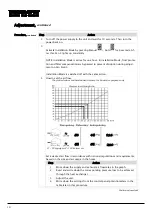
Activate Installation Mode by pressing Manual
+ Auto
for 6 seconds. Af-
ter this, Fan 3 lights up constantly.
NOTE: Installation Mode is active for one hour. In Installation Mode, frost protec-
tion and filter compensation are bypassed to prevent disruption during adjust-
ment on Fan Step 3.
Installation Mode is switched off with the same action.
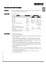
4 How to set the air flow.
Set a desired air flow in accordance with national regulations and requirements,
based on the size and air usage in the house:
Step
Action
1
Write down the supply and exhaust air flow rates in the graph.
2
Read and write down the corresponding pressure loss to be achieved
through the heat exchanger.
3
Adjust the unit.
4
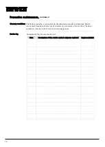
Write down the settings from the control panel potentiometers in the
table later in this procedure.
Continued overleaf
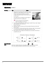
Pressure loss through the
heat exchanger
The plotted values and handwritten data are for illustrative purposes only
216
230
48
58
50
59
P1 - P2 Supply air P3 - P4 Extract air
Содержание HCV 5
Страница 1: ...HCV 4 HCV 5 Installation manual Rev 1 1 EN DA DE FR ...
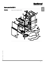
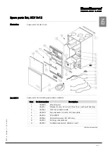
Страница 19: ...17 070719 Version 1 1 05 10 2012 EN Spare parts list HCV 4 Illustration Spare parts list illustration HCV 4 ...
Страница 32: ...30 Dimensions HCV 5v12 Unit dimensions The illustration shows the dimensions on an HCV 5v12 ...
Страница 64: ...30 Dimensioner HCV 5v12 Aggregatets dimen sioner Illustrationen viser dimensionerne på en HCV 5v12 ...
Страница 83: ...17 070719 Version 1 1 05 10 2012 DA DE Ersatzteilliste HCV 4 Abbildung Abbildung über Ersatzteile HCV 4 ...
Страница 96: ...30 Abmessungen HCV 5v12 Abmessungen des Geräts Die Abbildung zeigt die Abmessungen eines HCV 5v12 ...
Страница 116: ...18 Liste des pièces de rechange HCV 4 Illustration Illustration de la liste des pièces de rechange HCV 4 ...
Страница 130: ...32 Dimensions HCV 4 Dimensions de l appareil L illustration indique les dimensions du modèle HCV 4 ...
Страница 132: ...34 Schéma électrique Schéma Il s agit du schéma électrique des modèles HCV 4 HCV 5v12 ...
Страница 134: ...36 ...
Страница 136: ...2 Dantherm Air Handling A S Marienlystvej 65 7800 Skive Denmark www dantherm com service dantherm com 070719 070719 ...


