22
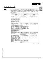
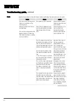
Troubleshooting guide,
continued
Faults
Identify the problem in the left-hand column and follow the instructions on the right:
Faults
Cause
Action
The unit is not running, and
there are no lights on the
control panel.
The power is not connected.
Check that the power
cable has been mount-
ed correctly.
Flashing red LED (120/min)
and beeping.
The unit has stopped and the
bypass damper is closed as
this fault constitutes a safety
risk (not HCV 4).
One of the temperature sen-
sors has detected a critically
high temperature of above
70°C.
Check that there is no
fire or other heat
sources that might
heat the pipe installa-
tions to above 70°C.
The T2 supply air sensor has
detected a temperature of be-
low 5°C, which constitutes a
risk of frost damage to the af-
terheat coil (optional extra).
Lack of duct insulation. Very
low outside temperature be-
low
-10°C. The house is not heat-
ed. The system has not been
adjusted correctly.
Examine the cause of
the low supply air
temperature and cor-
rect. Insulate the
ducts. Install pre-heat.
Carry out correct initial
adjustment. Activate
Installation Mode by
pressing Au-
to for 6 seconds. See
the section on initial
adjustment
The unit has been misaligned
so that there is gradient away
from the drain in the unit.
Straighten the unit so
that it hangs/stands
horizontally/vertically.
The drain is blocked in the
pipe or drip tray inside the
unit.
Check that the drain is
not blocked and clean,
if required, with water
and detergent.
The styrene front cover and/or
the plastic panel on the drip
tray have been unscrewed from
the unit and have not been re-
placed securely enough.
Check that the plastic
panel on the drip tray
and styrene front cover
have been installed
correctly so that they
are completely airtight
and watertight.
Continued overleaf
Содержание HCV 5
Страница 1: ...HCV 4 HCV 5 Installation manual Rev 1 1 EN DA DE FR ...
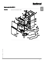
Страница 19: ...17 070719 Version 1 1 05 10 2012 EN Spare parts list HCV 4 Illustration Spare parts list illustration HCV 4 ...
Страница 32: ...30 Dimensions HCV 5v12 Unit dimensions The illustration shows the dimensions on an HCV 5v12 ...
Страница 64: ...30 Dimensioner HCV 5v12 Aggregatets dimen sioner Illustrationen viser dimensionerne på en HCV 5v12 ...
Страница 83: ...17 070719 Version 1 1 05 10 2012 DA DE Ersatzteilliste HCV 4 Abbildung Abbildung über Ersatzteile HCV 4 ...
Страница 96: ...30 Abmessungen HCV 5v12 Abmessungen des Geräts Die Abbildung zeigt die Abmessungen eines HCV 5v12 ...
Страница 116: ...18 Liste des pièces de rechange HCV 4 Illustration Illustration de la liste des pièces de rechange HCV 4 ...
Страница 130: ...32 Dimensions HCV 4 Dimensions de l appareil L illustration indique les dimensions du modèle HCV 4 ...
Страница 132: ...34 Schéma électrique Schéma Il s agit du schéma électrique des modèles HCV 4 HCV 5v12 ...
Страница 134: ...36 ...
Страница 136: ...2 Dantherm Air Handling A S Marienlystvej 65 7800 Skive Denmark www dantherm com service dantherm com 070719 070719 ...


