11
070719
•
Ve
rs
io
n
1
.1
•
0
5
.1
0
.2
0
1
2
EN
Adjustment,
continued
Procedure,
continued
Step
Action
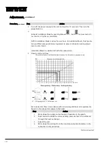
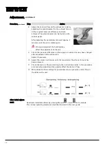
5 Install the manometer on pressure pipe P1
and P2 and measure the supply air pres-
sure loss through the heat exchanger.
P2
P1
6 Adjust the main air flow on the supply air
side by adjusting the potentiometer for
the supply air fan until the required pres-
sure difference has been achieved. The
potentiometer can be found on the con-
trol panel.
After adjusting the potentiometers, wait
approx. 2 minutes until the unit is stable
again.
Strong wind against the building may
affect the adjustment of the unit.
7 Connect the pressure manometer to the
pressure pipes P3 and P4 and measure the
pressure loss through the heat exchanger.
P3
P4
Continued overleaf
Содержание HCV 5
Страница 1: ...HCV 4 HCV 5 Installation manual Rev 1 1 EN DA DE FR ...
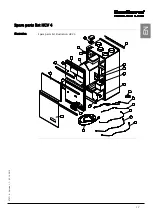
Страница 19: ...17 070719 Version 1 1 05 10 2012 EN Spare parts list HCV 4 Illustration Spare parts list illustration HCV 4 ...
Страница 32: ...30 Dimensions HCV 5v12 Unit dimensions The illustration shows the dimensions on an HCV 5v12 ...
Страница 64: ...30 Dimensioner HCV 5v12 Aggregatets dimen sioner Illustrationen viser dimensionerne på en HCV 5v12 ...
Страница 83: ...17 070719 Version 1 1 05 10 2012 DA DE Ersatzteilliste HCV 4 Abbildung Abbildung über Ersatzteile HCV 4 ...
Страница 96: ...30 Abmessungen HCV 5v12 Abmessungen des Geräts Die Abbildung zeigt die Abmessungen eines HCV 5v12 ...
Страница 116: ...18 Liste des pièces de rechange HCV 4 Illustration Illustration de la liste des pièces de rechange HCV 4 ...
Страница 130: ...32 Dimensions HCV 4 Dimensions de l appareil L illustration indique les dimensions du modèle HCV 4 ...
Страница 132: ...34 Schéma électrique Schéma Il s agit du schéma électrique des modèles HCV 4 HCV 5v12 ...
Страница 134: ...36 ...
Страница 136: ...2 Dantherm Air Handling A S Marienlystvej 65 7800 Skive Denmark www dantherm com service dantherm com 070719 070719 ...


