9
070719
•
Ve
rs
io
n
1
.1
•
0
5
.1
0
.2
0
1
2
EN
Adjustment
Introduction
This section guides you through the initial adjustment of the HCV unit
Important
Only trained and certified technicians are permitted to install the unit!
Legislation
Initial adjustment of air flow rates must always be carried out in accordance with na-
tional legislation. Only the nominal air flow requires initial adjustment. The nominal air
flow is Fan Step 3 in Manual Operation Mode on the control panel. More at Description
of the Control Panel' section in the user guide.
When
The unit must be adjusted in the following situations:
Before the unit is used for the first time
If the size of the house changes
If the house is renovated and the duct system is affected by the renovation
If the filter type is changed e.g. during the pollen season
Before you start
All air valves in the duct system must be set according to the manufacturer's/supplier's
recommendations before an initial adjustment of the HCV is commenced.
Ensure that you have the following at hand before you start the installation:
Pressure manometer with approx. 5 mm pipes matching the pressure connections
on the unit, which are 6 mm
Initial adjustment of
air flow
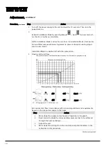
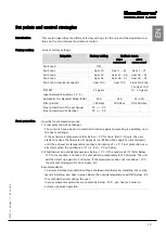
When the initial adjustment is carried out, it is important to ensure that the air flows are
the same!
Important:
The supply air flow (T2) must under no circumstances be higher than the extract air
flow (T3). If it is, it may mean that humid air is pressed into the building structure,
which can have a destructive effect on the building if the vapour shield is not 100% air-
tight.
Procedure
Follow this procedure to adjust the unit:
Step
Action
1
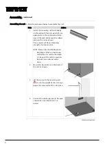
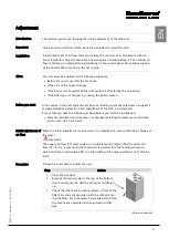
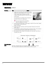
Open the top door
2
Remove the two screws on the top of the bottom
door and remove the door by tilting it and lifting it
up.
3
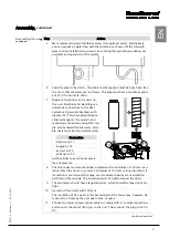
Check that the foam insulation plates in front of the
filters are correctly mounted with the soft side fac-
ing the filter. Push the plates firmly against the filter
to prevent any unwanted air being drawn in that
way.
Continued overleaf
Содержание HCV 5
Страница 1: ...HCV 4 HCV 5 Installation manual Rev 1 1 EN DA DE FR ...
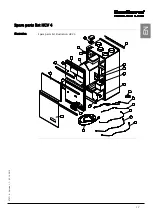
Страница 19: ...17 070719 Version 1 1 05 10 2012 EN Spare parts list HCV 4 Illustration Spare parts list illustration HCV 4 ...
Страница 32: ...30 Dimensions HCV 5v12 Unit dimensions The illustration shows the dimensions on an HCV 5v12 ...
Страница 64: ...30 Dimensioner HCV 5v12 Aggregatets dimen sioner Illustrationen viser dimensionerne på en HCV 5v12 ...
Страница 83: ...17 070719 Version 1 1 05 10 2012 DA DE Ersatzteilliste HCV 4 Abbildung Abbildung über Ersatzteile HCV 4 ...
Страница 96: ...30 Abmessungen HCV 5v12 Abmessungen des Geräts Die Abbildung zeigt die Abmessungen eines HCV 5v12 ...
Страница 116: ...18 Liste des pièces de rechange HCV 4 Illustration Illustration de la liste des pièces de rechange HCV 4 ...
Страница 130: ...32 Dimensions HCV 4 Dimensions de l appareil L illustration indique les dimensions du modèle HCV 4 ...
Страница 132: ...34 Schéma électrique Schéma Il s agit du schéma électrique des modèles HCV 4 HCV 5v12 ...
Страница 134: ...36 ...
Страница 136: ...2 Dantherm Air Handling A S Marienlystvej 65 7800 Skive Denmark www dantherm com service dantherm com 070719 070719 ...


