13
070719
•
Ve
rs
io
n
1
.1
•
0
5
.1
0
.2
0
1
2
EN
Set points and control strategies
Introduction
This section describes the different factory settings for the unit and the adjustment op-
tions on the control panel and remote control.
Factory setting
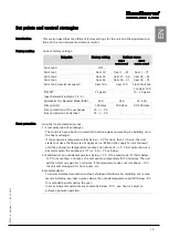
Current factory settings:
Set point
Factory setting
Settings range
HCP 4
control panel
HRC 2
remote control
Fan Step 0
OFF
-
-
Fan Step 1
Gear 14
Gear 1 - 41
Gear 1 - 71
Fan Step 2
Gear 39
Gear 21 - 66
Gear 36 - 81
Fan Step 3
Gear 64
Gear 46 - 91
Gear 46 - 91
Fan Step 4 (maximum speed)
Gear 100
Gear 100
From Fan Step
3 to Gear 100
'OFFSET'
(gear between Fan Steps 1-2-3)
25 gears
-
10 - 30 gears
Automatic On-Demand Mode (RH%)
45%
45%
35-65%
Filter period
180 days
180 days
90-360 days
Frost protection of the exchanger
Frost protection of afterheat
T4 ≤ + 2°C
T2 ≥ + 5°C
-
-
-
-
Frost protection
How the frost protection works:
1) Frost protection of exchanger.
The controls have a built-in protection function against preventing ice building up in
the heat exchanger.
If the exhaust air temperature falls below + 2°C for more than 1½ hours, the unit
starts to reduce the flow rate of supply air (i.e. RPM on the supply fan are reduced)
until the exhaust air temperature reaches a minimum of + 2°C. Frost protection usu-
ally starts when the outdoor air (T1) is -6 to -7°C or below.
2) Shutdown at an outside temperature below -13°C. If the outside air (T1) falls below -
13°C for more than 5 minutes, the unit will stop completely for 30 minutes. The unit
will then start up again for 5 minutes. If the temperature does not rise above -13°C,
the unit will stop again for 30 minutes, etc.
Recommendation
To ensure balanced ventilation without shutdown Dantherm Air Handling A/S recom-
mends installing pre-heat in areas where the outside temperature will fall below -6°C
for extended periods during the year.
In areas where temperatures are constantly below -13°C, pre-heat is a must to
achieve optimum operation.
Содержание HCV 5
Страница 1: ...HCV 4 HCV 5 Installation manual Rev 1 1 EN DA DE FR ...
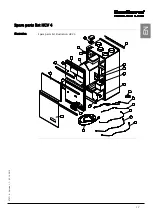
Страница 19: ...17 070719 Version 1 1 05 10 2012 EN Spare parts list HCV 4 Illustration Spare parts list illustration HCV 4 ...
Страница 32: ...30 Dimensions HCV 5v12 Unit dimensions The illustration shows the dimensions on an HCV 5v12 ...
Страница 64: ...30 Dimensioner HCV 5v12 Aggregatets dimen sioner Illustrationen viser dimensionerne på en HCV 5v12 ...
Страница 83: ...17 070719 Version 1 1 05 10 2012 DA DE Ersatzteilliste HCV 4 Abbildung Abbildung über Ersatzteile HCV 4 ...
Страница 96: ...30 Abmessungen HCV 5v12 Abmessungen des Geräts Die Abbildung zeigt die Abmessungen eines HCV 5v12 ...
Страница 116: ...18 Liste des pièces de rechange HCV 4 Illustration Illustration de la liste des pièces de rechange HCV 4 ...
Страница 130: ...32 Dimensions HCV 4 Dimensions de l appareil L illustration indique les dimensions du modèle HCV 4 ...
Страница 132: ...34 Schéma électrique Schéma Il s agit du schéma électrique des modèles HCV 4 HCV 5v12 ...
Страница 134: ...36 ...
Страница 136: ...2 Dantherm Air Handling A S Marienlystvej 65 7800 Skive Denmark www dantherm com service dantherm com 070719 070719 ...


