background image

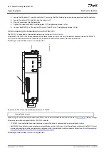
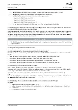
5.9.3.2 Connecting the Feed-In Cable

1

2

3

4

e30bg468.10

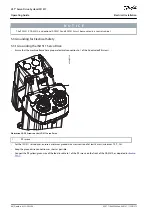
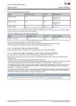
Illustration 32: Connectors on the Bottom of DAM 510

1

Ethernet connector

2

AUX connector

3

STO out connector

4

UDC connector

1

26

117

80

10

20

87

18

10

7

2
3

4

5

6

7

8

9

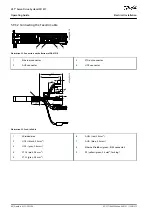
e30bg806.10

Illustration 33: Feed-In Cable

1

Shielded area

2

UDC+ (black, 2.5 mm

2

)

3

UDC– (gray, 2.5 mm

2

)

4

STO+ (pink, 0.5 mm

2

)

5

STO– (gray, 0.5 mm

2

)

6

AUX+ (red, 2.5 mm

2

)

7

AUX– (blue, 2.5 mm

2

)

8

Ethernet/fieldbus (green, RJ45 connector)

9

PE (yellow/green, 2.5 mm

2

, fork lug)

AQ377148425069en-000101

 / 130R1213


60 | Danfoss A/S © 2023.08

Electrical Installation

VLT® Servo Drive System ISD 511

Operating Guide

Содержание VLT ISD 511

Страница 1: ...Operating Guide VLT Servo Drive System ISD 511 drives danfoss com...

Страница 2: ......

Страница 3: ...Qualified Personnel 19 Due Diligence 19 Intended Use 19 Prohibited Application Areas 19 Forseeable Misuse 20 Service and Support 20 System Description 21 Overview of the ISD 511 System 21 Application...

Страница 4: ...LEDs 32 D Operation keys and reset 33 Mechanical Installation 34 Items Supplied 34 Transport 34 Inspection on Receipt 34 Safety Measures during Installation 34 Installation Environment 34 Overview 34...

Страница 5: ...ents 52 Connecting the ISD 511 Servo Drive 52 Electrical Installation Warnings for ISD 511 Servo Drive 52 General Instructions for Cable Installation 52 Disconnecting Hybrid Cables 56 Connecting the P...

Страница 6: ...mation Studio 69 Requirements for Programming with Automation Studio 69 Creating an Automation Studio Project 69 Including the Servo Motion Libraries into an Automation Studio Project 69 Constants wit...

Страница 7: ...onventions 90 Installation 91 Protective Measures 92 Application Example 92 Commissioning Test 92 Commissioning Test using Libraries 92 Operation of the STO Function 93 Error Codes 94 Fault Reset 94 F...

Страница 8: ...n Error Error 0x1000 0x100 100 Grounding Fault 100 Brake Resistor Error 100 Brake Chopper Error 101 Internal Fan Error 101 Error Codes for ISD 511 Servo System 101 No error 0x0000 0x0 101 Generic appl...

Страница 9: ...re Motor 0x4310 0x108 108 UAUX undervoltage 0x5112 0x109 108 Charge switch failure voltage 0x5121 0x158 108 Output phase U failure 0x5411 0x123 108 Output phase V failure 0x5412 0x124 108 Output phase...

Страница 10: ...0xFF70 0x11B 114 Firmware Power cycle needed 0xFF71 0x11C 114 Firmware Update started 0xFF72 0x11D 115 Firmware Update invalid 0xFF73 0x15B 115 STO active while drive enabled 0xFF80 0x11E 115 STO mism...

Страница 11: ...128 Characteristic Data for ISD 511 Servo Drive 128 Characteristic Data for Power Supply Module PSM 510 129 Characteristic Data for Decentral Access Module DAM 510 130 Characteristic Data for Auxiliar...

Страница 12: ...e 139 AC Mains Connector 140 Mains Cable Cross Sections for PSM 510 140 Relay Connector 140 Relay Connector on PSM 510 ACM 510 141 STO Connectors 141 STO Connectors on PSM 510 141 STO Connectors on th...

Страница 13: ...ervo Drive System ISD 510 DSD 510 MSD 510 VLT Flex motion Programming Guide Information about the programming of the ISD 511 servo sys tem 1 3 Copyright VLT and ISD are Danfoss registered trademarks 1...

Страница 14: ...Ethernet based fieldbus system PLCopen Technical specification Function blocks for motion control formerly Part 1 and Part 2 Version 2 0 March 17 2011 1 5 Firmware Updates For updates to the firmware...

Страница 15: ...ntroller external device for controlling the servo system PSM 510 Power Supply Module that generates a 565 680 V DC supply System modules Includes PSM 510 DAM 510 and the optional ACM 510 and EXM 510...

Страница 16: ...is a risk of death serious injury or damage to the unit Always comply with the instructions in this manual and national and local safety regulations W A R N I N G HIGH VOLTAGE The ISD 511 system cont...

Страница 17: ...operating condition A deficient operating condition may lead to death serious injury damage to equipment or other material damage when the unit is connected to the electrical supply network Take suit...

Страница 18: ...the specifications connection conditions and installation conditions in this manual is mandatory The safety regulations and safety provisions of the country in which the equipment is used must be obs...

Страница 19: ...g the control of machinery and equipment that are applicable at the place of use of the servo system are complied with The users always have all current information relevant to their interests about t...

Страница 20: ...tes misuse This also applies to failure to comply with the specified operating conditions and applications Danfoss assumes no liability of any sort for damage attributable to improper use 2 8 Service...

Страница 21: ...he ISD 511 is a high performance decentral servo motion solution In this decentral system the ISD 511 servo drives are operated in a DC group and controlled by a PLC The hybrid cables used in the serv...

Страница 22: ...fitted or installed Third party devices and equipment can only be used in consultation with Danfoss For security reasons do not connect the ISD 511 servo drive to the internet Only configure the ISD 5...

Страница 23: ...1 X T01C5 D6 E0 FS1 PL S03 T F087 N10 X C S G X M X X Table 5 Legend to Type Code 01 03 Product group 20 21 Bus system 35 Motor sealing ISD VLT Integrated Servo Drive PL Ethernet POWERLINK S With seal...

Страница 24: ...Warning at 130 C fault at 140 C minimum temperature 10 C Board temperature Warning at 105 C fault at 110 C 3 2 3 5 Built In Feedback Devices The built in feedback device measures the rotor position T...

Страница 25: ...rvo system It is used to connect the VLT Integrated Servo Drive ISD 511 to the servo system via a hybrid feed in cable The DAM 510 supplies the decentral servo drives with DC link UAUX STO and the Eth...

Страница 26: ...E20PLSXXXXXXXXXXXXX 1 2 3 4 5 e30bg582 11 Illustration 4 DAM 510 1 Connectors STO Ethernet and external encoder 2 Operating LEDs 3 LCP connector 4 PE screws 5 Connectors UDC AUX STO out and Ethernet 3...

Страница 27: ...XXXXXXXXXXX 1 2 3 4 e30bg583 10 CAP ST NET ST X1 X2 LCP LINK ACT DEV STATUS ACM Illustration 5 ACM 510 1 Connectors I O relay and Ethernet 2 Operating LEDs 3 LCP connector 4 PE screws 3 6 Expansion Mo...

Страница 28: ...according to IEC EN 60529 The EXM 510 may be damaged if exposed to fluids An example type code for the EXM 510 is MSD510EXM510F1C062AD6E20XXXXXXXXXXXXXXXX 3 7 Software The software for the servo syste...

Страница 29: ...les are not provided by Danfoss but must conform to the specifications detailed in Table 6 Table 6 Feed Cables Feed cable type Description Maximum length Cross section Feed in From DAM 510 to slip rin...

Страница 30: ...d can be used for commissioning and troubleshooting It can also be used to perform simple func tions for example activating and deactivating the output lines on the DAM 510 The LCP can be mounted on t...

Страница 31: ...10 11 12 13 14 15 16 17 18 19 20 21 Status e30bg799 10 Illustration 7 Display Area when Connected to the PSM 510 and DAM 510 1 UAUX line voltage 2 Temperature power board 3 Actual UDC current 4 Power...

Страница 32: ...or menu access for parameter set up toggling through status display modes during normal operation and viewing fault log data Table 8 Display Menu Keys Key Function 6 Status Shows operational informati...

Страница 33: ...flash and an alarm text is shown 3 10 2 4 D Operation keys and reset The operation keys are located at the bottom of the LCP Table 11 Operation Keys and Reset Key Function 18 Hand On Enables the conn...

Страница 34: ...esentative if there are visible defects or the delivery is incomplete 4 4 Safety Measures during Installation Always observe the safety instructions in this manual during installation Pay particular a...

Страница 35: ...he bearings and the coupling components and reduces heat transfer from the servo drive Ensure that the seal is not bum ped when inserting the drive into the machine as that could damage the seal resul...

Страница 36: ...1 1 Minimum Distance for M23 Angled Connector Illustration 10 shows the minimum distance from the servo drive to the next object For cable installation connecting disconnecting the M23 angled connecto...

Страница 37: ...bottom for cooling 270 10 63 3 94 3 3 15 6 1 0 24 14 4 0 28 1 18 max 100 min 85 min 30 1 57 min 40 6 367 7 max 120 4 72 e30bg820 10 380 min 155 Illustration 11 Minimum Space Required at the Top and B...

Страница 38: ...included are required 4 7 4 Fitting Instructions for ISD 511 Servo Drive 4 7 4 1 Overview The ISD 511 servo drives are delivered with plastic M23 protection caps and a shaft protection cap These plast...

Страница 39: ...the roundtable from the bottom see Illustration 13 and the top see Illustration 14 e30bk052 10 4 x M6 x 40 Illustration 13 Mounting the ISD 511 from the Bottom AQ377148425069en 000101 130R1213 39 Dan...

Страница 40: ...ottom M6 15 mm in the roundtable 7 8 5 Nm N O T I C E The fixing screws are not supplied See 11 3 2 Dimensions of Flange Screw for Mounting the ISD 511 Servo Drive 4 7 5 Fitting Instructions for Syste...

Страница 41: ...cap via the click and lock method 1 e30bg802 10 Illustration 15 Connecting the Backplates 1 Backplate End Cap AQ377148425069en 000101 130R1213 41 Danfoss A S 2023 08 Mechanical Installation VLT Servo...

Страница 42: ...sher diameter of 9 5 mm The tightening torque is 3 Nm e30bg803 10 Illustration 16 Mounting the Backplates in the Control Cabinet Slide the module onto the carrier at the bottom of the backplate AQ3771...

Страница 43: ...re the module pull down the holding clamp 1 in Illustration 18 at the top of the backplate 1 e30bg815 10 STATUS PSM DEV SVS ST NET ST LINK ACT X1 X2 STATUS DAM DEV SVS ST NET ST AUX LINK ACT X1 X2 X3...

Страница 44: ...f the 2nd module is inside the guiding groove at the right side of the 1st module 1 in Illustration 19 1 e30bg822 10 Illustration 19 Guiding Groove 1 Guiding groove AQ377148425069en 000101 130R1213 44...

Страница 45: ...rs disconnecting or connecting the cable disconnect the PSM 510 from the mains and wait for the discharge time to elapse 5 2 Electrical Environmental Conditions Compliance with the following electrica...

Страница 46: ...0 Illustration 20 PE Screws on the ISD 511 Servo Drive 1 PE screws For the ISD 511 servo drives ensure a minimum ground wire cross section of at least 4 mm2 minimum 70 C Cu Keep the ground wire connec...

Страница 47: ...can be used to loop the earthing conductor for a maximum of 5 units If the system uses more than 5 units ground them in groups of 5 5 3 2 Grounding the System Modules Do not ground the system modules...

Страница 48: ...h UL requirements Keep the ground wire connections as short as possible Follow the wiring requirements in the VLT Multiaxis Servo Drive System MSD 510 Operating Guide N O T I C E If 2 separate backlin...

Страница 49: ...Bottom of the System Modules 1 Cable tie 2 EMC metal shielding plate 3 EMC plate screw Use a cable with a shielding that has a high coverage to reduce electrical interference Do not use pigtails to co...

Страница 50: ...Grounded 3 phase mains network 400 480 V AC 10 3 phase lines and PE line 3 phase frequency 44 66 Hz Maximum input current for 1 PSM 510 at 30 kW 55 Arms 5 5 1 Fuses N O T I C E Use fuses on the suppl...

Страница 51: ...oltage used 2 If the maximum current is lower a fuse with lower current rating can be used Rating of UL fuses according to 125 of maximum current Use a time delay fuse rated according to the DC voltag...

Страница 52: ...DC link capacitors that remain charged for some time after the mains supply is switched off at the Power Supply Module PSM 510 Failure to wait the specified time after power has been removed before pe...

Страница 53: ...onnector towards the electronic housing on the servo drive until the sealing on the connector is entirely cov ered Tighten the M23 feed in cable connector by rotating the threaded ring clockwise out o...

Страница 54: ...e servo drives in daisy chain format connect the male connector of the loop cable to the female connector X2 of the 1st servo drive Connect the female connector of the loop cable to the male connector...

Страница 55: ...es in Daisy Chain Format X1 Male connector X2 Female connector 1 M23 metal blind cap Screw the M23 metal blind cap onto the unused M23 female output connector X2 on the last servo drive in the servo s...

Страница 56: ...tor of the feed in cable from the Decentral Access Module DAM 510 Rotate the threaded ring on the feed in cable connector on the servo drive counterclockwise until the marking OPEN on the cable connec...

Страница 57: ...modules When 2 PSM 510 modules are used the wiring between the AC line choke and each PSM 510 must be the same length within a tolerance of 0 5 m Connect each PSM 510 to the AC choke directly Parallel...

Страница 58: ...or X1 IN 1 Connect the Ethernet cable from the Ethernet output connector X2 OUT 2 to the next module Insert the wires into the 24 48 V IN INPUT 24 48 V connector Insert the 24 48 V IN connector 3 Inse...

Страница 59: ...ide 3 and a PE wire The tightening torque is 3 Nm 5 9 3 Connecting the Decentral Access Module DAM 510 5 9 3 1 Connecting the Cables on the Top of the Decentral Access Module DAM 510 1 2 3 4 5 e30bg46...

Страница 60: ...7 18 10 7 2 3 4 5 6 7 8 9 e30bg806 10 Illustration 33 Feed In Cable 1 Shielded area 2 UDC black 2 5 mm2 3 UDC gray 2 5 mm2 4 STO pink 0 5 mm2 5 STO gray 0 5 mm2 6 AUX red 2 5 mm2 7 AUX blue 2 5 mm2 8...

Страница 61: ...e RJ45 bus connector 2 Connect the DAM 510 to PE using one of the PE screws on the front side 1 and a PE wire The tightening torque is 3 Nm Connect the PE wire of the feed in cable to the other PE scr...

Страница 62: ...o PE using one of the PE screws on the front side 5 and a PE wire The tightening torque is 3 Nm AQ377148425069en 000101 130R1213 62 Danfoss A S 2023 08 Electrical Installation VLT Servo Drive System I...

Страница 63: ...cables 4 Functional earth cable 5 GND cable 6 24 48 V cable 7 Cable ties N O T I C E If 2 separate backlinks are used connected via 1 or 2 pairs of EXM 510 modules the 2 grounding bars must be also co...

Страница 64: ...e resistors is not permitted STATUS PSM DEV SVS ST NET ST LINK ACT X1 X2 LCP 1 e30bh423 10 PSM 510 Illustration 38 Connection of Internal Brake Resistor on 1 PSM 510 1 Internal brake resistor When usi...

Страница 65: ...NK ACT X1 X2 LCP 1 1 e30bh424 10 PSM 510 PSM 510 Illustration 39 Connection of Brake Resistor on 2 PSM 510 Modules in Parallel 1 Internal brake resistor AQ377148425069en 000101 130R1213 65 Danfoss A S...

Страница 66: ...511 servo drives to be established Switch on the mains Set the PSM 510 to state Normal operation Set the DAM 510 to state Normal operation Now the PSM 510 DAM 510 and the ISD 511 servo drives are read...

Страница 67: ...the fieldbus network On DAM 510 port X2 will be used automatically Select parameter 54 12 Epl ID assignment start id then select a valid value between 1 and 239 The value will be assigned to the devic...

Страница 68: ...selected port is position index 1 and so on Select parameter 54 07 Epl ID assignment direction and select between 0 ascending and 1 descending Select parameter 54 03 Automatic Epl ID assignment start...

Страница 69: ...files are required to integrate the ISD 511 servo drives and the PSM 510 and DAM 510 into an Automation Studio project Package of libraries for the MSD 510 servo system VLT_FlexMotion_Automation_Studi...

Страница 70: ...e names of the POUs that target the ACM 510 all end with _ACM DDS_BasCam Contains POUs for the creation of basic CAMs DDS_LabCam Contains POUs for the creation of labeling CAMs DDS_Intern Contains POU...

Страница 71: ...unction block DD_ReadDamError_DAM and or DD_ReadDamWarning_DAM DAM_TraceSignals Constants for the trace signals of the Decentral Access Module DAM 510 Intended to be used with the function block DD_Tr...

Страница 72: ...dule DAM 510 that has to be controlled or monitored To create a link to the physical DAM 510 link each instance of DAM_REF to 1 physical DAM 510 This makes it the logical representation of 1 physical...

Страница 73: ...ck on the device and select Node Number Change Node Number e30bk876 10 Illustration 41 Adding a Servo Drive to the Project 6 5 10 Importing PSM 510 DAM 510 and ACM 510 into Automation Studio N O T I C...

Страница 74: ...els section change the Cyclic transmission of the following objects All sub indexes of object 0x5050 Lib pdo rx_I5050 ARRAY to Write All sub indexes of object 0x5051 Lib pdo tx_I5051 ARRAY to Read Par...

Страница 75: ...found in the I O configuration of the device e30bg341 10 Illustration 43 I O Configuration of an ISD 511 Device e30bg342 10 Illustration 44 I O Mapping after Successful Configuration AQ377148425069en...

Страница 76: ...right clicking PLK Configuration in the Physical View N O T I C E Ensure that the task cycle times of the PLC program and Ethernet POWERLINK are the same Otherwise data could be lost and performance r...

Страница 77: ...ference to the axis on a function block while it is busy N O T I C E The full parameter list can be found in the VLT Servo Drive System ISD 510 DSD 510 MSD 510 VLT Flexmotion Pro gramming Guide 6 6 VL...

Страница 78: ...cation 6 6 4 1 Overview This chapter describes the Ethernet specific network interface settings needed by the VLT Servo Toolbox There are 2 basic com munication methods direct communication and indire...

Страница 79: ...e communication through a PLC the VLT Servo Toolbox configures a routing table using the selected Net work Address Translation NAT Adding a route to the Windows routing table requires administrator pr...

Страница 80: ...vity from a high level software perspective and does not reflect the actual physical topology of the network 6 6 4 4 2 Network Settings for Direct Communication with Ethernet POWERLINK Disable all net...

Страница 81: ...settings Right click on the network interface used for fieldbus communication and select Properties Click on Internet Protocol Version 4 TCP IPv4 the checkbox must be checked and then click on Proper...

Страница 82: ...ling behaviour of the outputs General calling conventions N O T I C E See the VLT Servo Drive System ISD 510 DSD 510 MSD 510 VLT Flexmotion Programming Guide for further infor mation on the available...

Страница 83: ...AM mode In CAM mode the servo drive executes a synchronized movement based on a master axis The synchroniza tion takes place via a CAM profile that contains slave positions corresponding to master pos...

Страница 84: ...voltage is not applied SVS ST Green On 24 V safety supply is applied Off 24 V safety supply is not applied NET ST Green red Fieldbus de pendent Network status of the device see corresponding fieldbus...

Страница 85: ...n 24 V safety supply is applied Off 24 V safety supply is not applied NET ST Green red Fieldbus depend ent Network status of the device see corresponding fieldbus stand ard 1 LINK ACT X1 Link activity...

Страница 86: ...s of the device see corresponding fieldbus standard 1 AUX State of the auxiliary voltage Green On Auxiliary voltage is applied to the output connector Off Auxiliary voltage is not applied to the outpu...

Страница 87: ...Device is in state Fault or Fault reaction active Flashing DC link is not applied at the input CAP ST Green On Capacitors fully charged Flashing Capacitors charging discharging Off Capacitors dischar...

Страница 88: ...Description Link activity status of Out Off No link 1 POWERLINK Refer to the corresponding fieldbus standard AQ377148425069en 000101 130R1213 88 Danfoss A S 2023 08 Operation VLT Servo Drive System I...

Страница 89: ...ts Failure to isolate the mains voltage supply and wait for the specified discharge time to elapse could result in death or serious injury Only perform work on electrical parts of the system or the IS...

Страница 90: ...k analysis of the application The overall safety of the application Identifying safety functions required and allocating SIL or PL to each of the functions other subsystems and the validity of sig nal...

Страница 91: ...rom other suppliers can be used for the user connection to the STO terminal STO DAM Pins 3 and 4 on the Decentral Access Module DAM 510 Safety relays that have a plus and minus switching output signal...

Страница 92: ...e 3 Emergency stop button 4 Safety device contacts 5 Decentral Access Module DAM 510 6 Hybrid cable 7 Feed in cable 8a Servo drive 8b Servo drive 9 Loop cable 8 8 Commissioning Test N O T I C E Perfor...

Страница 93: ...does not run 9 Disable STO Check that the STO start is still inhibited by the error sig nal MC_ReadAxisInfo_DDS output SafeTorqueOff False and MC_ReadStatus_DDS output ErrorStop True 10 Try to run th...

Страница 94: ...o compare the fault of all servo drives on 1 line Error code 0xFF81 0x11F means that there is a fault on the servo drive that can only be reset by carrying out a power cycle Com plete the commissionin...

Страница 95: ...er Accessibility Maintenance Test the STO safety function at least once per year as follows Remove the STO input voltage Verify that the motors stop running Verify that no unexpected error codes appea...

Страница 96: ...ectively Type number Error code Firmware version System setup for example number of servo drives system modules and lines System status when the fault occurred Ambient conditions 9 2 Troubleshooting f...

Страница 97: ...ter settings Contact Danfoss 9 2 7 Uneven Running Possible cause Defective bearing Troubleshooting Check the shaft 9 2 8 Vibration Possible cause Defective bearing Incorrect control loop parameters Tr...

Страница 98: ...10 DAM 510 and ACM 510 Possible causes Missing input power Missing or open fuses or circuit breaker tripped No power to the LCP Incorrect contrast setting Display is defective Troubleshooting Table 26...

Страница 99: ...e servo drive current consumption Avoid simultaneous acceleration of all servo drives Decrease the acceleration value 9 3 5 High Cont Power Overload Error 0x2313 0x161 This fault applies to the PSM 51...

Страница 100: ...3 11 Generic Application Error Error 0x1000 0x100 This error is valid for PSM 510 DAM 510 ACM 510 and ISD 511 Possible causes A generic error has occurred in the application Troubleshooting Contact D...

Страница 101: ...000 0x0 Code PROFINET code Name Severity warning error trip lock Description LCP name 0x0000 0x0 No error Error No error 9 4 2 Generic application error 0x1000 0x100 This error is valid for PSM 510 DA...

Страница 102: ...on LCP name 0x2330 0x151 Ground fault Warning error Discharge from output phases to ground ground fault 9 4 7 AUX overcurrent 0x2391 0x125 This error is valid for DAM 510 Table 33 AUX overcurr 0x2391...

Страница 103: ...lock Description LCP name 0x2396 0x15C Current overload trip Error Current overload trip error curr ovld trip 9 4 12 Power overload trip 0x2397 0x12B This error is valid for PSM 510 Table 38 Power ove...

Страница 104: ...52 DC link charg ing error Error DC link charging error The maximum time limit to charge the DC link has been ex ceeded UDC charg ing 9 4 17 DC Link unbalanced 0x3280 0x153 This error is valid for PSM...

Страница 105: ...rvolt age Error UAUX below undervoltage limit UAUX undervolt 9 4 22 DC link high voltage 0x3295 0x136 This error is valid for PSM 510 DAM 510 and ACM 510 Table 48 DC link high voltage 0x3295 0x136 Cod...

Страница 106: ...r Error Error when UAUX is in shut down phase UAUX shtdwn err 9 4 27 UAUX undervoltage hardware 0x329A 0x156 This error is valid for PSM 510 DAM 510 and ACM 510 Table 53 UAUX undervoltage hardware 0x3...

Страница 107: ...ity warning error trip lock Description LCP name 0x4291 0x106 Overtemperature Control card Error Maximum temperature of con trol card exceeded overtemp CC 9 4 32 Overtemperature Power card 0x4292 0x10...

Страница 108: ...AUX under voltage Error trip lock Undervoltage on auxiliary voltage Undervolt UAUX 9 4 37 Charge switch failure voltage 0x5121 0x158 This error is valid for PSM 510 Table 63 Charge switch failure volt...

Страница 109: ...pa rameter missing Trip lock EEPROM checksum error or missing device parameter Contact Danfoss eeprom err 9 4 42 Parameter error 0x6320 0x10B This error is valid for PSM 510 DAM 510 ACM 510 and ISD 51...

Страница 110: ...ailure Warning error The brake chopper is monitored during oper ation A brake failure has been detected by the brake check function brake ch fail 9 4 47 Brake chopper overcurrent 0x7112 0x167 This err...

Страница 111: ...ch high volt 9 4 51 Internal position sensor error 0x7320 0x10C This error is valid for ISD 511 Table 77 Internal position sensor error 0x7320 0x10C Code PROFINET code Name Severity warning error tri...

Страница 112: ...de PROFINET code Name Severity warning error trip lock Description LCP name 0x8694 0x110 Homing error on start homing method Warning Could not start homing method for example drive not in stand still...

Страница 113: ...nfoss timing err 1 9 4 62 Timing violation 2 0xFF61 0x116 This error is valid for ISD 511 Table 88 Timing violation 2 0xFF61 0x116 Code PROFINET code Name Severity warning error trip lock Description...

Страница 114: ...Code PROFINET code Name Severity warning error trip lock Description LCP name 0xFF67 0x16B Timing violation 8 Trip lock Contact Danfoss timing err 8 9 4 69 Timing violation 9 0xFF68 0x16C This error...

Страница 115: ...3 0x15B Code PROFINET code Name Severity warning error trip lock Description LCP name 0xFF73 0x15B Firmware Up date invalid Error Invalid or corrupted firmware package update Last valid firmware packa...

Страница 116: ...Increments between succeeding values too large guide val impl 9 4 79 UDU GV out of range 0xFF92 0x291 This error is valid for ISD 511 Table 105 UDU GV out of range 0xFF92 0x291 Code PROFINET code Nam...

Страница 117: ...e 0 to abs Gmin Gmax UDU Min Blending distance out of range 9 4 82 Sign of life error 0xFF95 0x14E This error is valid for ISD 511 Table 108 Sign of life error 0xFF95 0x14E Code PROFINET code Name Sev...

Страница 118: ...out any maintenance work on the servo system or replacing components Minimum waiting time minutes 15 10 2 Inspection during Operation 10 2 1 ISD 511 Servo Drives Carry out regular inspections during o...

Страница 119: ...y cle and check the STO func tion Every 12 months Activate STO and check the status with the PLC 2 A shorter interval may be necessary depending on the application Contact Danfoss for more information...

Страница 120: ...on the I O shielding plate 3 Pull the I O shielding plate upwards to remove it Release the securing clamp 1 at the top of the module 1 e30bg815 10 STATUS PSM DEV SVS ST NET ST LINK ACT X1 X2 STATUS DA...

Страница 121: ...itching on the ISD 511 System Configure the system module s parameters according to the fieldbus used Conduct a test run 10 6 Cable Replacement 10 6 1 Overview Replace the cables when the rated number...

Страница 122: ...ed in cable with a cable binder Secure the STO cable with a cable binder Mount the EMC plate on the DAM 510 Connect the PE wire to the PE screw on the DAM 510 Reconnect any cables that were connected...

Страница 123: ...1 e30bg800 10 Illustration 61 Opening the Cover on DAM 510 Use a screwdriver to remove the fuses and replace them with the same number of identical type fuses e30bg801 10 Illustration 62 Removing the...

Страница 124: ...rthermore foreign materials or third party components cannot be included with the returned product Ship the products free on board to the local Danfoss sales company 10 10 Recycling Take metals and pl...

Страница 125: ...om of ISD 511 1 Supply voltage 2 Nominal torque 3 Maximum torque 4 Ambient temperature range 5 Protection rating 6 Typecode 7 Auxiliary input voltage 8 Rated speed 9 Customer part number S N 123401Q12...

Страница 126: ...5GXXXX Serial no 002901Q092 Output Pnom 10kW 00 1B 08 33 2C 3D 00 1B 08 33 2C 3E 00 1B 08 33 2C 3F DANGER 15 MIN Motor over temperature sensing is required Cust no 0906279896 VLT PSM 510 MAC PSM X1 IN...

Страница 127: ...5A Ambient 5 40 C 41 104 F PART NO 175GXXXX SERIAL NO 018301Q052 MAC DAM 00 1B 08 32 E7 02 175GXXXX018301Q052 Made in Italy Danfoss A S 6430 Nordborg Denmark Danfoss Ltd Oxford Road UB9 4LH Denham UK...

Страница 128: ...S1 at 400 RPM Tamb 45 C Stall torque M0 Nm 2 1 Stall current motor I0 A 1 1 Maximum speed nMAX RPM 1000 Maximum torque MMAX Nm 10 S3 at 400 RPM 5 ED 1 5 s Maximum current motor IMAX A 6 S3 at 400 RPM...

Страница 129: ...umption at 24 V DC A DC 2 0 UAUX current consumption at 48 V DC A DC 1 0 Output DC link voltage V DC 565 680 10 DC link capacitance F 1800 Rated current IN A 20 40 60 Rated power PN kW 10 20 30 Peak p...

Страница 130: ...umption at 48 V DC A DC 0 3 Output Output voltage V DC VOUT PSM Output current DC link A DC 15 25 Peak current DC link rms value t 1 0 s Arms 30 for 1 s 48 for 1 s Output current UAUX A DC 15 General...

Страница 131: ...current A DC 62 Mounting Wall mounted on backplate using backlink connector Weight kg 0 6 Dimensions W x H x D mm 87 x 380 x 145 11 3 Dimensions 11 3 1 Dimensions of ISD 511 Servo Drive All dimension...

Страница 132: ...sions are in mm in 2x 5 2 0 2 6 0 24 367 14 45 406 3 16 380 14 96 2x 5 2 0 2 7 0 28 21 3 0 84 270 10 63 100 3 94 137 3 5 41 25 0 98 50 1 97 25 0 98 16 0 63 e30bg586 10 STATUS PSM DEV SVS ST NET ST LIN...

Страница 133: ...2 0 2 e30bg587 10 STATUS DAM DEV SVS ST NET ST AUX LINK ACT X1 X2 X3 LCP Illustration 73 Dimensions of DAM 510 11 3 5 Dimensions of Auxiliary Capacitors Module ACM 510 All dimensions are in mm in AQ3...

Страница 134: ...M 510 11 3 6 Dimensions of Expansion Module EXM 510 All dimensions are in mm in 87 3 3 43 144 75 5 70 50 1 97 16 0 62 21 3 0 84 367 14 44 380 14 96 25 0 98 25 0 98 5 2 0 2 5 2 0 2 6 0 24 7 0 27 e30bi3...

Страница 135: ...um axial and radial load while assembling the motor and for any mechanical device connected to the shaft must not exceed the values shown in Table 115 The shaft must be loaded slowly and in a constant...

Страница 136: ...nment of Backlink Connector Table 116 Pin Assignment of Backlink Connector Pin Description 1 24 48 V 2 GND 3 FE Functional earth 4 DC 5 DC AQ377148425069en 000101 130R1213 136 Danfoss A S 2023 08 Spec...

Страница 137: ...N O T I C E The maximum length of the brake cable is 30 m shielded 11 6 3 Ethernet Connectors There are ethernet connectors on all the system modules e30be395 10 8 1 Illustration 79 Ethernet Connector...

Страница 138: ...igital input Galvanic isolated Input voltage 0 30 V DC High logic 1 voltage 15 30 V DC Low logic 0 voltage 5 V DC Maximum input signal frequency 50 Hz Maximum input current at 48 V 11 mA Maximum input...

Страница 139: ...A U T I O N POSSIBLE LOSS OF FUNCTIONAL SAFETY PROTECTION The functional safety feature may be affected if the UAUX input exceeds 60 V Ensure that the UAUX input remains below 60 V 11 6 5 1 24 48 V Ca...

Страница 140: ...escrip tion Notes Rating parameter 1 L3 Used to connect L1 L2 L3 Nominal voltage 400 480 V AC 10 Nominal power 30 kW Maximum cross section 16 mm2 AWG 4 Conductor cross section range 0 75 16 mm2 solid...

Страница 141: ...510 REL PSM and ACM 510 REL ACM Pins Description Notes Rating parameter 11 NC Normally closed 24 V DC Nominal current 2 A Conductor cross section range 0 2 1 5 mm2 AWG 24 AWG 16 12 NO Normally open 24...

Страница 142: ...of servo drives in the applica tion Maximum current 1 A Conductor cross section range 0 2 1 5 mm2 AWG 24 AWG 16 2 STO 3 STO Used for STO input voltage 4 STO N O T I C E Only PELV potential can be conn...

Страница 143: ...tage 24 V DC 10 Nominal current Depends on the number of servo drives in the applica tion Maximum current 1 A Conductor cross section range 0 2 1 5 mm2 AWG 24 AWG 16 2 STO 3 STO Used for STO input vol...

Страница 144: ...the bottom of the Decentral Access Module DAM 510 e30bg455 10 Illustration 90 UDC Connector Table 129 Pin Assignment of UDC Connector Pins left to right De scrip tion Notes Rating parameter 1 UDC Used...

Страница 145: ...6 Nm 4 43 5 31 in lb 2 AUX GND N O T I C E Only PELV potential can be connected to the AUX output 11 6 12 External Encoder Connectors DAM 510 E DAM 5 1 6 9 e30bg461 10 Illustration 92 External Encode...

Страница 146: ...nnected to the external encoder 11 6 13 Expansion Module Connector e30bh390 10 DC DC GND 24 V 48 V Illustration 93 Expansion Module Connector Table 133 Pin Assignment of Expansion Module Connector Pin...

Страница 147: ...24 V functional PE 16 mm2 minimum 70 C Cu 6 AWG minimum 90 C Cu 1 1 Minimum 75 C is allowed if less than 45 A is measured on the cable 11 7 Connectors on the ISD 511 Servo Drives 11 7 1 X1 and X2 Hyb...

Страница 148: ...supply 24 V DC 10 1 A 3 STO Safety supply ground 5 TD Positive Ethernet transmit According to standard 100BASE T 6 RD Positive Ethernet receive 7 TD Negative Ethernet transmit 8 RD Negative Ethernet r...

Страница 149: ...les is not fulfilled if the modules are not connected to the backplate This may result in death or seri ous injury Do not touch the backplate when a module is removed from the backplate Vibration test...

Страница 150: ...ee location with low vibration veff 0 2 mm s The storage location must be free from corrosive gases Avoid sudden temperature changes Long term storage To recondition the electrolytic capacitors servo...

Страница 151: ...3 D DAM_REF Automation Studio 72 DAM 510 overview 25 Digital CAM switch 83 Dimensions ISD 511 servo drive 131 PSM 510 132 DAM 510 132 ACM 510 133 EXM 510 134 Direct communication 80 Discharge time 17...

Страница 152: ...SM_REF Automation Studio 72 PSM 510 Overview 24 Q Qualified personnel 19 R Recycling 124 Relay connector 140 S Safety during installation 34 Safety instructions 18 Safety supply requirements 51 Servic...

Страница 153: ...n e V CE European test and certification mark CIA DS 402 Device profile for drives and motion control CIA is a registered community trademark of CAN in Automation e V Clamping set A mechanical device...

Страница 154: ...for connecting the hybrid feed in and loop cables on the B side of the ISD 511 servo drive Motor shaft Rotating shaft on the A side of the servo motor typically without a key groove Multi turn encode...

Страница 155: ...ich the absolute position for 1 revolu tion remains known Standstill servo drive Power is on there is no error in the axis and there are no motion com mands active on the axis System modules This term...

Страница 156: ...rinted material Danfoss reserves the right to alter its products without notice This also applies to products already on order provided that such alterations can be made without subsequential changes...

Отзывы: