


-
Provide a good high-frequency
connection between the motor and the
frequency converter. Use a shielded
cable that has a 360° connection in the
motor and the frequency converter.
-
Ensure that the impedance from the
frequency converter to building ground
is lower that the grounding impedance
of the machine. This procedure can be
difficult for pumps.
-
Make a direct ground connection
between the motor and load motor.
•
Lower the IGBT switching frequency.
•
Modify the inverter waveform, 60° AVM vs.
SFAVM.
•
Install a shaft grounding system or use an
isolating coupling.
•
Apply conductive lubrication.
•
Use minimum speed settings if possible.
•
Try to ensure that the mains voltage is balanced
to ground. This procedure can be difficult for IT,
TT, TN-CS, or grounded leg systems.
•
Use a dU/dt or sine-wave filter.
10.4 Motor Thermal Protection
The electronic thermal relay in the frequency converter has
received UL-approval for single motor protection, when
parameter 1-90 Motor Thermal Protection
is set for
ETR Trip
and
parameter 1-24 Motor Current
is set to the rated motor
current (see the motor nameplate).
For motor thermal protection, it is also possible to use the
VLT
®
PTC Thermistor Card MCB 112 option. This card
provides ATEX certificate to protect motors in explosion
hazardous areas, Zone 1/21 and Zone 2/22. When
parameter 1-90 Motor Thermal Protection
, set to
[20] ATEX
ETR
, is combined with the use of MCB 112, it is possible to
control an Ex-e motor in explosion hazardous areas.
Consult the
programming guide
for details on how to set
up the frequency converter for safe operation of Ex-e
motors.
10.4.1 Types of Thermal Protection
10.4.1.1 PTC Thermistor
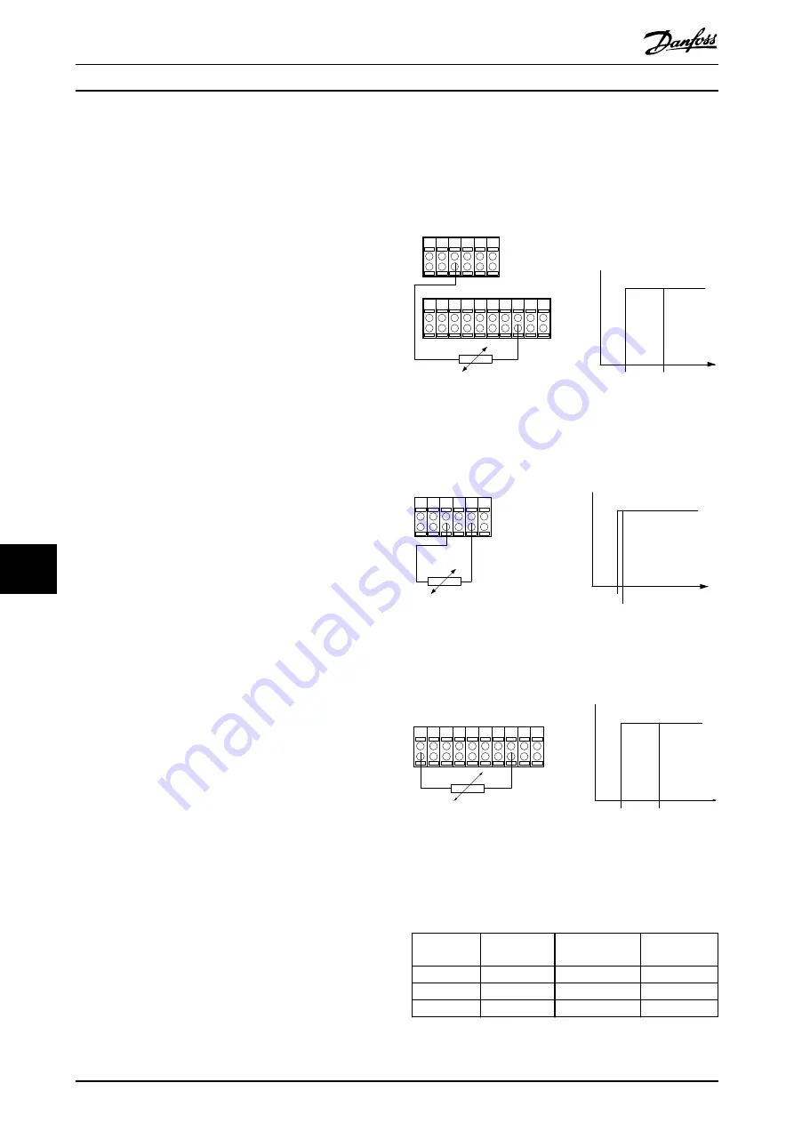
Using a digital input and 10 V supply
PTC / Thermistor
R
OFF
ON
<800 Ω
+10V
130BA152.10
>2.7 kΩ
12 13
18
37
32
27
19
29
33 20
55
50
39 42
53 54
Illustration 10.2 PTC Thermistor Connection - Digital Input
with 10 V Supply
Using an analog input and 10 V supply
55
50
39 42
53 54
R
<3.0 k
Ω
>3.0 k
Ω
+10V
130BA153.11
PTC / Thermistor
OFF
ON
Illustration 10.3 PTC Thermistor Connection - Analog Input
with 10 V Supply
Using a digital input and 24 V as supply
PTC / Thermistor
OFF
ON
+24V
12 13 18
37
32
A
27
19
29
33
B
20
GND
R
<6.6 k Ω >10.8 k Ω
130BA151.11
Illustration 10.4 PTC Thermistor Connection - Digital Input
with 24 V Supply
Check that the selected supply voltage follows the specifi-
cation of the used thermistor element.
Input digital/
analog
Supply
voltage [V]
Trip resistance
k
Ω
Reset
resistance
Digital
10
>2.7
<800
Ω
Analog
10
>3.0
<3.0 k
Ω
Digital
24
>10.8
<6.6 k
Ω
Table 10.2 PTC Thermistor Resistance Parameters
Motor
VLT
®
Parallel Drive Modules
106
Danfoss A/S © 6/2016 All rights reserved.
MG37N102
10
10


