VFD500 high performance vector control frequency inverter user manual Chapter 5 function code table
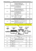
P30.11
Data sent by
Master
0:output frequency
1:set frequency
2:output torque
3:set torque
4:PID setting
5:PID feedback
6:output current
0
☆
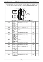
P30.12
Sending
interval of
Master
0.010
~
10.000sAs a master, after sending
one frame of data, the next frame of data is
sent after this delay.
0.1s
☆
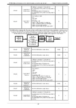
P30.13
Receiving
proportaionalit
y factor of
slave
-10.000
~
10.000The values of slave registers
0x7001 and 0x7002 take effect after passing
through this scaling factor
1.00
☆
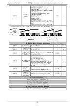
P30.14
Communicatio
n special
register speed
unit
0: 0.01%
1: 0.01Hz
2: 1Rpm
Some units of specific communication
registers can be set by this parameter. See
Appendix A for details.
0
☆
P30.15
Modbus
response
characteristics
When the format of the received frame is a
write register, this parameter can be set to
reply to the host.
0: Reply to the host (standard Modbus
protocol)
1: Do not reply to the host (non-standard
Modbus protocol)
0
☆
31 Group Canopen communication parameter
P31.00
C A N o p e n
communicatio
n address
1 ~ 127
1
☆
P31.01
C A N o p e n
Baud rate
0
:
100k
1
:
125k
2
:
250k
3
:
500k
4
:
1M
3
☆
P31.02
C A N o p e n
overtime
1ms ~ 20ms
4ms
☆
r31.07
C A N o p e n
v e r s i o n
number
Display the version number of the CANopen
card
-
●
r31.08
C A N o p e n
Working status
0: Initialisation status
1: Disconnected
2: Connecting/Preparing-
3: Stopped
4: Operational status
5: Pre_operational
-
●
r31.10
C A N o p e n
receive error
count
The number of error frames received by
CANopen is not saved after power off
-
●
r31.11
C A N o p e n
s e n d e r r o r
count
The number of frames sent by CANopen is not
saved after power off
-
●
r31.12
C A N o p e n
receive frame
number
The number of frames received by CANopen
is not saved after power off
-
●
95


