


Steering Device Signals
Index
Default
Mapping Set Value
Steering wheel angle signal (Priority 1)
65101
0
0 - not present
255 - present on CAN
High priority steering device (Priority 2)
65102
0
0 - not present
1 - present at AD1
2 - present at AD2
4 - present at CAN
Low priority steering device (Priority 3)
65103
0
0 - not present
1 - present at AD1
2 - present at AD2
4 - present at CAN
Primary steered wheel (or actuator) signal
65104
0
0 - not present
1 - present at AD1
2 - present at AD2
4 - present at CAN
High priority set-point controller (Priority 4)
65105
0
0 - not present
255 - present on CAN
Redundant steered wheel sensor signal
65107
0
0 - not present
255 - present on the same interface type
Vehicle speed signal
65108
0
0 - not present
255 - present on CAN
OSP signal
65109
0
0 - not present
255 - present hydraulically
When mapping the vehicle speed sensor, the CAN source address of the vehicle speed sensor shall be
configured correspondingly in the VehicleSpeedSensorSourceAddress parameter. See
on page 107.
Only one signal per analogue channel can be acquired
Mapping the OSP signal serves only the purpose to monitor the PVED for conflicting setpoints when
steering by steering wheel using the EHPS valve with hydraulic back up. Other parameter conflicts are
mentioned appendix
A mapped device can be de-activated by means of sending a DeviceDisableCommand as mentioned in
chapters
High Priority Steering Device Enable/Disable Control
The High priority set-point controller can similarly be de-activated. Please refer to
PVED-CL
Communication Protocol
, 11079551.
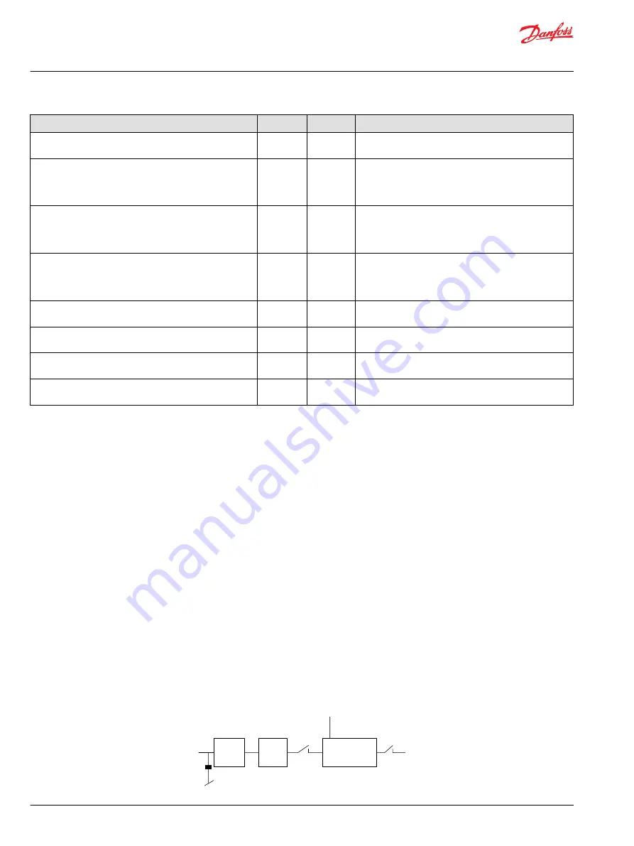
Analogue Interface
A 200 Hz first-order low-pass filter is applied before the AD sampling. Both analogue voltage signals at
AD1 and AD2 are converted into a digital value between 0 and 1023 [AD full scale]. A running average
filter, which takes 5 consecutive samples per 5 ms, removes high frequent noise. In case a redundant
steered wheel angle sensor occupies both analogue inputs, comparison between both scaled values is
made.
Block diagram of processing analogue to digital converted signals
200 Hz
sampler
1000 Hz
sampler
Init
P005 222E
Analogue signal
range: 0 to 5 V DC
Pre-filter
(low pass)
200 Hz
10-bit
A/D
Raw analog to digital
converted signals
range: 0 to 1023
Running average
filter:
N = 5, dt = 1ms
Pull down resistor
Operation Manual
PVED-CL Controller for Electro-Hydraulic Steering, Version 1.38
Installation
32 |
©
Danfoss | May 2016
11025583 | AQ00000216en-US0302