Vision manual page:8
0dB on the meters 10dBu on the outputs!
If V.U. reading led bars are ordered, they will have attack and release times of 300msec. and a
+4 dBu level on the output connectors will give a 0 dB reading on the meter.
Measuring the +4 dB output level of the channel or master with a AC voltmeter would give a 1.22 volt
reading. The LED meter would actually be reading -6 dB on the scale. When monitoring program
material, you will see higher levels on the peak reading meters.
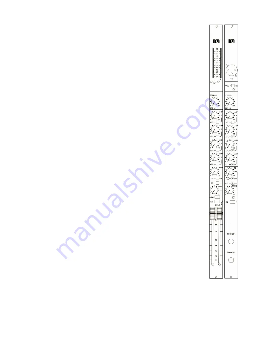
2.5 Talkback section
The talkback section allows all communication functions from the control room to the
Aux Sends and
GROUPS.
The unbalanced talk back input (wired balanced) can be routed to the 4/8 aux sends, all group outputs
and main outputs by activating the
ALL
switch. The Aux 1-2 switch only routes the TB signal to
the Aux 1-2 busses. In both cases the CRM output is dimmed by 20 dB.
The talkback switch is a momentary type which allows you to talk to the above mentioned outputs.
2.6 Auxiliary masters
The auxiliary master sections are identical in function. The first module controls the Aux send busses 1,
2, 3, & 4 and the second module controls Aux send busses 5, 6, 7, & 8. Each Aux master pot controls
the sum of all channel or group aux send busses. The solo switch sends the (post fader) aux buss
signal to the control room monitors. The master SOLO LED indicates the activated solo switch.
2.7 Phones section
The
PHONES
section performs in a similar way to the CRM section.
The phones output simply follows the control room monitor output but with its own level control.
2.8 Stereo return sections
The Vision console has a stereo return control in both the master output modules.
The stereo signal is directly assigned to the master left/right busses.


