Safety and system checks
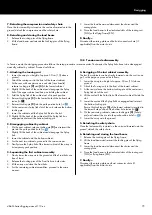
Before hoisting the array to its operating position, recheck the
actual status of the assembly. When applicable, the same safety
and system checks also apply to ground stack assemblies.
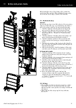
11.1 Mechanical setup
General
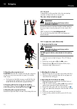
Be aware that any object or tool left on the top of the array during
setup may fall when the array is operated. Always check that no
tools or other objects are left on the array before final hoisting.
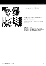
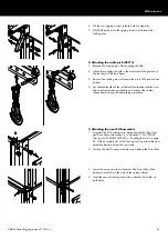
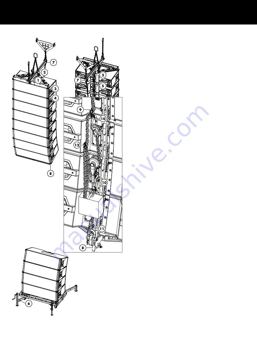
1. Check the attachment of the load beam to the flying frame
and ensure all Locking pins are fully inserted and locked.
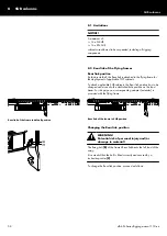
2. Check the attachment of the secondary safety device at the
Chapter 3.14 "Secondary safety"
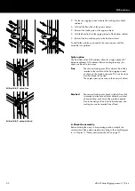
3. Check the attachment of the flying frame to the cabinets and
ensure all Locking pins are fully inserted and locked.
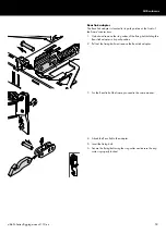
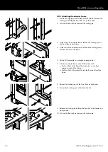
4. Check the attachment of all Front links on both sides of the
cabinets and ensure all Locking pins are fully inserted and
locked.
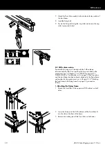
5. Check the splay angles and the attachment of the Splay/Rear
links at the rear of the cabinets and ensure all Locking pins are
fully inserted and locked.
6. With ground stack setups, check the attachment of the outrig
rods and ensure all Socket pins are fully inserted and locked.
In Compression mode
7. Check the attachment of the compression chain's coupling
shackle to the load beam and ensure the Locking pin is fully
inserted and locked.
8. Check the attachment of the compression frame and ensure all
Locking pins are fully inserted and locked.
9. Check the position and attachment of the compression grab
link and ensure the safety latch is locked.
10. Check the attachment of the lever hoist to the O-ring of the
compression grab link and compression frame master link and
ensure both safety latches of the hooks are closed.
11. Check the attachment of the compression frame master link to
the shackle of the compression frame and ensure the safety
latch of the hook is closed.
12. Ensure the grab link of the second chain leg of the
compression frame master link is properly attached to the
compression chain and the safety latch is locked (refer to
Chapter 6 "Compression mode setup"
11.2 Wiring
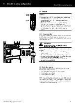
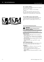
▪ If the amplifiers are already wired and powered on, use their
System check functions or channel mute switches and a test
signal to check the correct operation and routing of all channels
and cabinets.
▪ Alternatively check the wiring using the Array verification
function in R1.
11 Safety and system checks
d&b SL-Series Rigging manual 1.10 en
71
Содержание SL Series
Страница 1: ...SLSL Series Rigging manual 1 10 en ...
Страница 9: ...SL Series rigging modes 2 in 1 Tension mode principle d b SL Series Rigging manual 1 10 en 9 ...
Страница 10: ...SL Series rigging modes 2 in 1 Compression mode principle Preset d b SL Series Rigging manual 1 10 en 10 ...
Страница 79: ...D2734 EN 01 10 2020 d b audiotechnik GmbH Co KG www dbaudio com ...

