Derigging
13.1 General
To dismantle any of the assemblies, follow the corresponding
assembly and setup instructions in reverse order.
The same safety instructions apply!
WARNING!
Potential risk of personal injury and/or
damage to material!
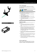
In particular, make sure that when lowering and decompressing
the array nobody is directly underneath or in the vicinity of the
array.
When lowering the array,
avoid diagonal pull.
This could lead to the potential risk of the array tipping over
towards the front.
13.2 Compression mode disassembly
1. Decompressing the array
WARNING!
Potential risk of personal injury and/or
damage to material.
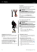
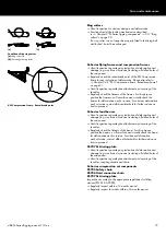
Do NOT operate the free chain knob [1] in lowering
mode.
1. Lower the array to a height of approx. 30 cm (1 ft) above
ground.
2. Set the lever mode selector
[2] to the DN position.
3. Operate the lever
[3] counterclockwise until the array is
completely straight (decompressed).
2. Detaching the compression set
Small hint: Apart from the compression frame, the compression
set items can remain interconnected and stored. This simplifies
further setups.
Þ
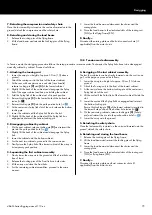
For this purpose, detach the compression grab link from the
compression chain and the hook of the compression frame
master link from the shackle of the compression frame.
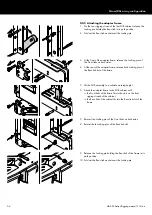
3. Preparing the first four cabinets for loading
Change the position of Locking pin
[3] from its splay angle hole
back to the lowest hole of the bottom hole index (
Þ
).
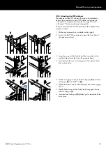
4. Detaching the compression frame
Detach the compression frame in reverse order starting at the rear.
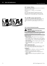
5. Attaching the touring cart
1. Reattach the touring cart in reverse order starting at the front.
2. Lift the rear of the cart until the Splay link has engaged and
reinsert the bottom locking pin.
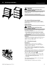
6. Separating the first cabinet assembly
1. Slowly lower the array onto the ground until the Front and
Splay links are free of load.
2. At the rear, release Locking pin
[1] and [2] of the uppermost
cabinet of the assembly and fold out the Splay link.
3. Reinsert the Locking pins to the same hole positions (
Þ
).
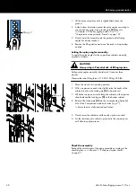
4. At the front, release the Locking pins of the Front links on both
sides.
5. Lift the array and store the Front links.
6. For the remaining cabinet assemblies, proceed in the same
manner.
13 Derigging
d&b SL-Series Rigging manual 1.10 en
74
Содержание SL Series
Страница 1: ...SLSL Series Rigging manual 1 10 en ...
Страница 9: ...SL Series rigging modes 2 in 1 Tension mode principle d b SL Series Rigging manual 1 10 en 9 ...
Страница 10: ...SL Series rigging modes 2 in 1 Compression mode principle Preset d b SL Series Rigging manual 1 10 en 10 ...
Страница 79: ...D2734 EN 01 10 2020 d b audiotechnik GmbH Co KG www dbaudio com ...

