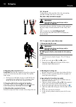
SUB columns
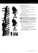
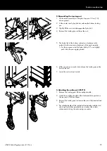
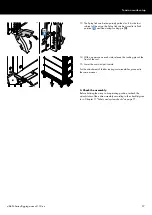
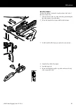
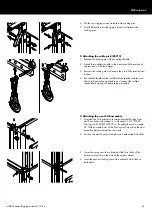
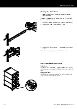
7. Attach the Rear link assembly to the dedicated hole position of
the load beam.
8. Insert the fixing bolt.
9. Secure the fixing bolt using the ring cotter and ensure the ring
cotter is properly locked.
8.3 SUB column setup
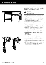
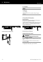
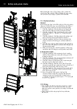
Provided the Touring cart is loaded with the SUB cabinets
interconnected by their Front and Rear links as described in the
previous section
Chapter 3.16.2 "E7492 Touring cart SL-
"Loading the cart" on page 39 and in position
and the load beam has been already attached to the flying frame
as described in the previous section
the load beam to the flying frame" on page 45, proceed as
follows:
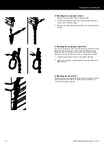
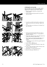
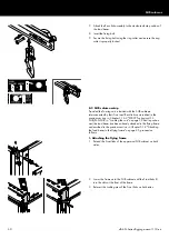
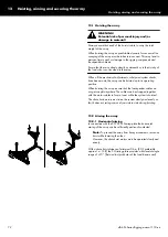
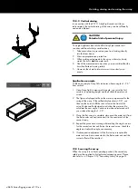
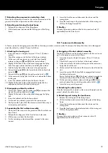
1. Attaching the flying frame
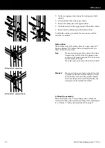
1. Extend the Front links of the uppermost SUB cabinet on both
sides.
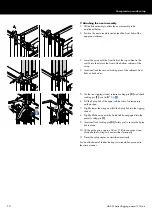
2. Lower the frame onto the SUB cabinet until the Front links fit
into the slots at the front of the frame.
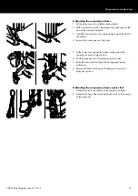
3. Reinsert the Locking pins of the Front links on both sides.
d&b SL-Series Rigging manual 1.10 en
60
Содержание SL Series
Страница 1: ...SLSL Series Rigging manual 1 10 en ...
Страница 9: ...SL Series rigging modes 2 in 1 Tension mode principle d b SL Series Rigging manual 1 10 en 9 ...
Страница 10: ...SL Series rigging modes 2 in 1 Compression mode principle Preset d b SL Series Rigging manual 1 10 en 10 ...
Страница 79: ...D2734 EN 01 10 2020 d b audiotechnik GmbH Co KG www dbaudio com ...


