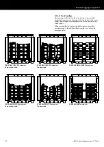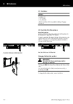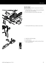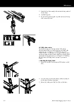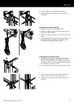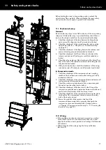
Tension mode setup
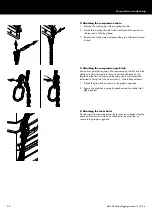
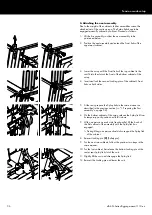
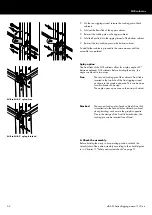
4. Attaching the next assembly
Due to the weight of the cabinets, further assemblies cannot be
attached out of the cart in one go. The Splay links have to be
engaged manually cabinet by cabinet. Proceed as follows:
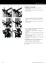
1. Lift the first assembly to allow the next assembly to be
positioned below.
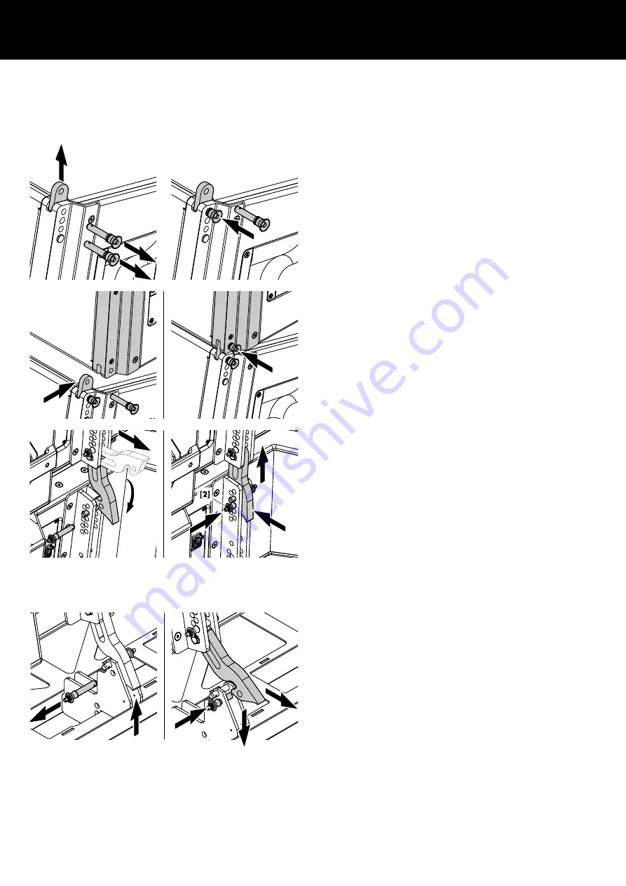
2. Position the next assembly and extend the Front links of the
uppermost cabinet.
3. Lower the array until the Front links of the top cabinet in the
cart fit into the slots at the front of the bottom cabinet of the
array.
4. Insert and lock the second Locking pins of the cabinet's Front
links on both sides.
5. At the rear, prepare the Splay links in the same manner as
described in the previous section (
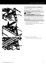
6. On the bottom cabinet of the array, release the Splay link from
its temporary park position and fold it down.
7. With one person on each side (rear handle), lift the back of
the first cabinet of the assembly until the Splay link has
engaged.
↳During lifting, one person should also support the Splay link
of the cabinet.
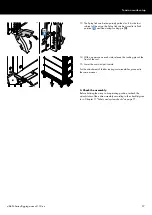
8. Reinsert Locking pin
[2] (Safety pin).
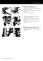
9. For the next two cabinets, follow the previous two steps in the
same manner.
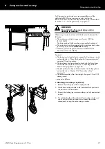
10. For the last cabinet, first release the bottom Locking pin at the
center rear Splay link slot of the cart.
11. Slightly lift the cart and disengage the Splay link.
12. Reinsert the Locking pin and lower the cart.
d&b SL-Series Rigging manual 1.10 en
56
Содержание SL Series
Страница 1: ...SLSL Series Rigging manual 1 10 en ...
Страница 9: ...SL Series rigging modes 2 in 1 Tension mode principle d b SL Series Rigging manual 1 10 en 9 ...
Страница 10: ...SL Series rigging modes 2 in 1 Compression mode principle Preset d b SL Series Rigging manual 1 10 en 10 ...
Страница 79: ...D2734 EN 01 10 2020 d b audiotechnik GmbH Co KG www dbaudio com ...

