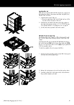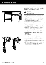
Tension mode setup
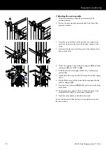
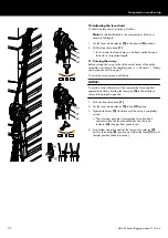
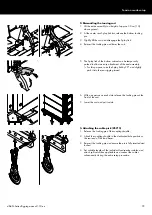
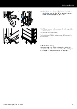
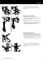
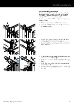
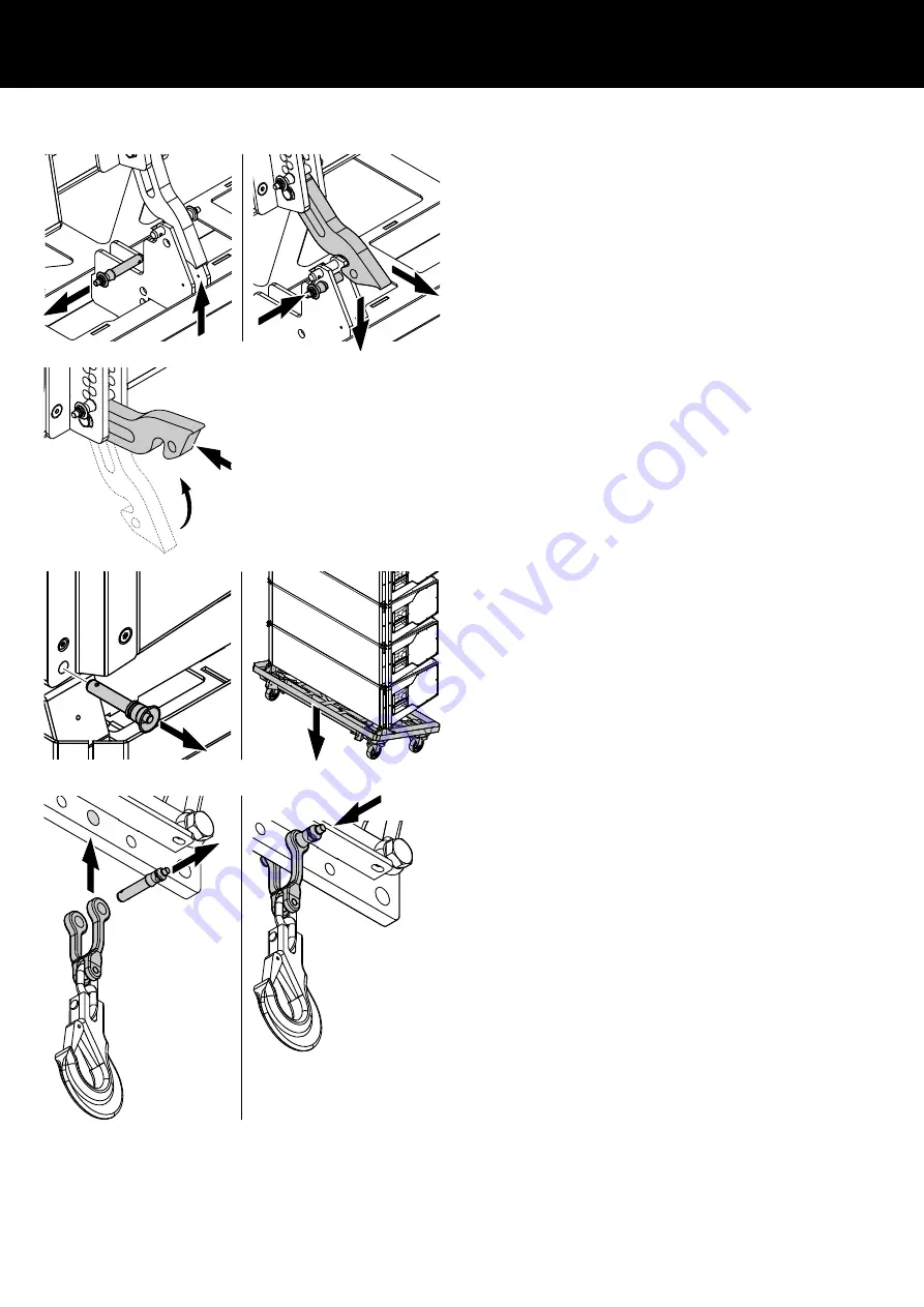
2. Dismantling the touring cart
1. Lift the entire assembly to a height of approx. 30 cm (1 ft)
above ground.
2. At the center rear Splay link slot, release the bottom Locking
pin.
3. Slightly lift the cart and disengage the Splay link.
4. Reinsert the Locking pin and lower the cart.
5. The Splay link of the bottom cabinet can be temporarily
parked to allow an easy attachment of the next assembly.
↳For this purpose, raise the Splay link by 90° and slightly
push it into the rear rigging strand.
6. With one person on each side, release the Locking pins at the
front of the cart.
7. Lower the cart and put it aside.
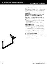
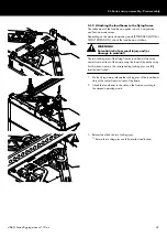
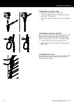
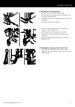
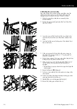
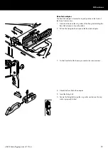
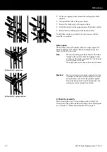
3. Attaching the cable pick (Z5713)
1. Release the Locking pin of the coupling shackle.
2. Attach the coupling shackle to the dedicated hole position at
the rear end of the load beam.
3. Reinsert the Locking pin and ensure the pin is fully inserted and
locked.
4. Set suitable lengths of the individual loudspeaker cables, and
attach split sets when applicable and connect the cables
subsequently during the entire setup procedure.
d&b SL-Series Rigging manual 1.10 en
55
Содержание SL Series
Страница 1: ...SLSL Series Rigging manual 1 10 en ...
Страница 9: ...SL Series rigging modes 2 in 1 Tension mode principle d b SL Series Rigging manual 1 10 en 9 ...
Страница 10: ...SL Series rigging modes 2 in 1 Compression mode principle Preset d b SL Series Rigging manual 1 10 en 10 ...
Страница 79: ...D2734 EN 01 10 2020 d b audiotechnik GmbH Co KG www dbaudio com ...

