18
Installing the X64-AN Quad
X64-AN Quad User's Manual
Upgrading both Sapera and Board Driver
When both Sapera LT and the Teledyne DALSA acquisition board driver are upgraded, follow the
procedure described below.
Logon the computer as an administrator or with an account that has administrator privileges.
In
Windows XP
, from the start menu select
Start • Settings • Control Panel • Add or Remove
Programs
. Select the Teledyne DALSA X64-AN Quad board driver and click
Remove
. Follow
by also removing the older version of Sapera LT.
In
Windows Vista and Windows 7
, from the start menu select
Start • Settings • Control Panel •
Programs and Features
. Double-click the Teledyne DALSA X64-AN Quad board driver and
click
Remove
. Follow by also removing the older version of Sapera LT.
Reboot the computer and logon the computer as an administrator again.
Install the new versions of Sapera and the board driver as if this was a first time installation. See
“
Sapera LT Library Installation
” on page 10
and
“
” on page 9
for installation
procedures.
Connecting Camera and Devices
Connector Bracket End View
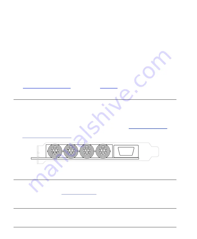
The following figure identifies the four X64-AN Quad input connectors. The Hirose-12 connectors
have programmable signal pins, defined by camera file parameters. See
“
page 63
for pinout descriptions. The DB9 connector J5 provides for easy trigger signal connections.
See
J5 – Trigger Signals Connector
” on page 65
for pinout descriptions.
Input 2
Input 3
Input 4
Input 1
J5 - I/O
Figure 6: X64-AN Quad Connector Bracket
Note:
An X64-AN Quad board is able to provide up to 500mA of power to connected cameras from
the PCI bus (fused protected). Nonetheless, Teledyne DALSA strongly recommends connecting the
floppy power connector (see
” on page 69
) to ensure sufficient current is
available from the PC power supply.
Caution:
Sinking more than 500mA from the X64-AN Quad PCI connector may result in the auto-
reset fuse blowing. Check your camera datasheet for the required camera current.


