

SiBE341001
Troubleshooting by Remote Controller
Troubleshooting
190
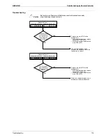
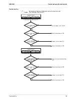
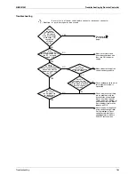
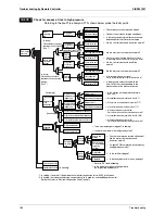
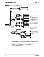
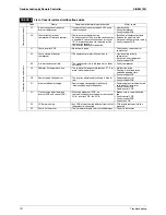
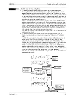
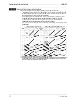
Check for causes of drop in low pressure
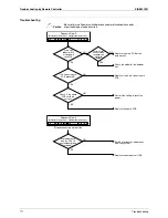
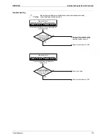
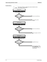
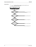
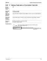
Referring to the Fault Tree Analysis (FTA) shown below, probe the faulty points.
CHECK 2
Faulty low
pressure
control
←
Are the electrical characteristics normal?
Abnormally low
low-pressure (Low
evaporating
temperature)
Faulty electronic
expansion valve
control
[In both cooling
and heating]
(See *2.)
[In cooling]
If the indoor unit
electronic
expansion valve is
excessively
throttled: (See *3.)
[In heating]
If the outdoor unit
electronic
expansion valve
excessively
throttled:
(See *4.)
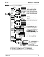
[In cooling]
Low suction
air
temperature
of the
evaporator
[In heating]
Less
circulation
quantity of
refrigerant
Degradation
in condensing
capacity
[In cooling]
(See *1.)
Faulty
compressor
capacity
control
Faulty low
pressure
protection control
Faulty indoor unit
electronic
expansion valve
Faulty
control
Faulty outdoor
unit electronic
expansion valve
Faulty
control
Low suction air
temperature of
indoor unit
Faulty suction air thermistor of indoor unit
Low suction air temperature of outdoor unit
Faulty outdoor temperature thermistor of outdoor unit
High pipe
resistance
Inadequate refrigerant quantity
Moisture choke
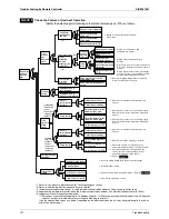
Dirty evaporator
Decreased
fan airflow
rate
Decreased
fan output
High air
passage
resistance
Abnormal piping length
Bent or crashed pipe
Clogging of foreign particles
Stop valve closed
Faulty fan motor
Faulty control PCB
(Including capacity setting)
Dirty filter
Obstacle
Faulty low pressure sensor
Faulty control PCB
Faulty low pressure sensor
Faulty hot gas solenoid valve
Faulty control PCB
Faulty valve coil
Faulty valve body
Faulty gas pipe
thermistor of indoor unit
Faulty liquid pipe thermistor
of indoor unit
Faulty control PCB
Faulty valve coil
Faulty valve body
Faulty low pressure sensor
Faulty suction pipe thermistor
Faulty control PCB
Short circuit
Low ambient temperature
←
Is the pressure value checked with the Service Checker
corresponding to the measurement of the pressure sensor?
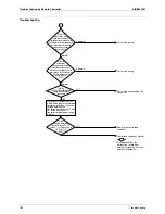
←
Is the pressure value checked with the Service Checker
corresponding to the measurement of the pressure sensor?
←
Are the electrical characteristics normal?
←
Are the coil resistance and insulation normal?
←
Is the pressure value checked with the Service Checker
corresponding to the measurement of the pressure sensor?
←
Are the coil resistance and insulation normal?
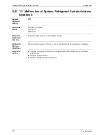
←
Check for the thermistor resistance and
connection.
←
Check for the thermistor resistance and
connection.
←
Is the pressure value checked with the Service Checker
corresponding to the measurement of the pressure sensor?
←
Are the coil resistance and insulation normal?
←
Are the electrical characteristics normal?
←
Check for the thermistor resistance and
connection.
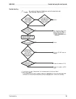
←
Is the suction air temperature not less than 14°C
←
Is the indoor temperature not more than 14°C
←
Is the connector properly connected?
Are the thermistor resistance characteristics normal?
←
Is the outdoor temperature more than -20°C
←
Is the connector properly connected?
Are the thermistor resistance characteristics normal?
←
Is the connector properly connected?
Are the thermistor resistance characteristics normal?
←
Does the piping length fall in the permissible range?
←
Conduct visual checks for pipe conditions.
←
Is there any temperature difference caused
before and after the filter or branch pipe?
←
Eliminate moisture by vacuum operation.
←
Is the heat exchanger clogged?
←
Can the fan motor be rotated with hands?
Are the motor coil resistance and insulation normal?
←
If a spare PCB is mounted, is the
capacity setting properly made?
←
Is the air filter clogged?
←
Is there any obstacle in the air passage?
*1: For details of the compressor capacity control while in cooling, refer to “Compressor PI Control”.
*2: The “low pressure protection control” includes low pressure protection control and hot gas bypass control.
*3: In cooling, the indoor unit electronic expansion valve is used for “superheated degree control”.
*4: In heating, the outdoor unit electronic expansion valve (EVM) is used for “superheated degree control of
outdoor unit heat exchanger”.
←
Check to be sure the stop valve is open.
Содержание RQYQ140-180PY1
Страница 15: ...SiBE341001 Specifications 6 Part 2 Specifications 1 Specifications 7 1 1 Outdoor Units 7 1 2 BS Units 16...
Страница 215: ...SiBE341001 Piping Diagrams Appendix 206 1 Piping Diagrams 1 1 Outdoor Unit RQYQ140 180PY1 RQEQ140 180 212PY1 3d066010A...
Страница 216: ...Piping Diagrams SiBE341001 207 Appendix 1 2 BS Unit BSVQ100 160 250PV1 4D057985B...
Страница 217: ...SiBE341001 Piping Diagrams Appendix 208 BSV4Q100PV1 3D064148...
Страница 218: ...Piping Diagrams SiBE341001 209 Appendix BSV6Q100PV1 3D064149...
Страница 220: ...Wiring Diagrams for Reference SiBE341001 211 Appendix 2 2 BS Unit BSVQ100 160 250PV1 3D055928C...
Страница 221: ...SiBE341001 Wiring Diagrams for Reference Appendix 212 BSV4Q100PV1 3D063928B...
Страница 222: ...Wiring Diagrams for Reference SiBE341001 213 Appendix BSV6Q100PV1 3D063929B...
Страница 223: ...SiBE341001 Option List Appendix 214 3 Option List 3 1 Option Lists Outdoor Unit 3D066354...
Страница 224: ...Option List SiBE341001 215 Appendix...