

SiBE341001
Troubleshooting
92
Part 6
Troubleshooting
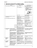
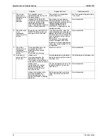
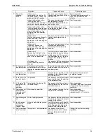
1. Symptom-based Troubleshooting .........................................................94
2. Troubleshooting by Remote Controller .................................................97
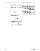
2.1
The INSPECTION / TEST Button...........................................................97
2.2
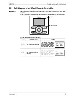
Self-diagnosis by Wired Remote Controller ...........................................98
2.3
Remote Controller Service Mode ...........................................................99
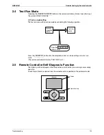
2.4
Test Run Mode.....................................................................................102
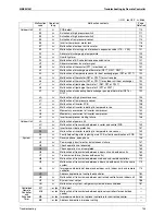
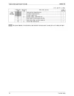
2.5
Remote Controller Self-Diagnosis Function .........................................102
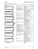
2.6
“
E1
” Outdoor Unit: PCB Defect .............................................................110
2.7
“
E2
” Outdoor Unit: Actuation of High Pressure Switch..........................111
2.8
“
E3
” Outdoor Unit: Actuation of High Pressure Switch..........................112
2.9
“
E4
” Outdoor Unit: Actuation of Low Pressure Sensor..........................114
2.10 “
E5
” Outdoor Unit: Inverter Compressor Motor Lock.............................116
2.11 “
E7
” Outdoor Unit: Malfunction of Outdoor Unit Fan Motor ...................118
2.12 “
E9
” Outdoor Unit: Malfunction of Electronic
Expansion Valve Coil (Y1E~Y3E) ........................................................121
2.13 “
F3
” Outdoor Unit: Abnormal Discharge Pipe Temperature..................123
2.14 “
F4
” Outdoor Unit: Humidity alarm ........................................................125
2.15 “
F9
” Outdoor Unit : Malfunction of BS Unit Electronic
Expansion Valve...................................................................................127
2.16 “
H7
” Outdoor Unit: Abnormal Outdoor Fan Motor Signal ......................129
2.17 “
H9
” Outdoor Unit: Malfunction of Thermistor (R1T) for Outdoor Air.....131
2.18 “
J3
,
J4
,
J5
,
J6
,
J7
,
J8
,
J9
” Outdoor Unit: Malfunction of
Outdoor unit Thermistor .......................................................................132
2.19 “
JA
” Outdoor Unit: Malfunction of High Pressure Sensor......................134
2.20 “
JC
” Outdoor Unit: Malfunction of Low Pressure Sensor ......................136
2.21 “
L1
” Outdoor Unit: Malfunction of Inverter PCB ....................................138
2.22 “
L4
” Outdoor Unit: Malfunction of Inverter Radiating Fin
Temperature Rise.................................................................................140
2.23 “
L5
” Outdoor Unit: Momentary Overcurrent of Inverter Compressor ....142
2.24 “
L8
” Outdoor Unit: Momentary Overcurrent of Inverter Compressor ....144
2.25 “
L9
” Outdoor Unit: Inverter Compressor Starting Failure ......................146
2.26 “
LC
” Outdoor Unit: Malfunction of Transmission between Inverter
and Main PCB ......................................................................................149
2.27 “
P1
” Outdoor Unit: Inverter Over-Ripple Protection...............................151
2.28 “
P4
” Outdoor Unit: Malfunction of Inverter Radiating Fin
Temperature Rise Sensor ....................................................................153
2.29 “
PJ
” Outdoor Unit: Faulty Field Setting after Replacing Main PCB
or Faulty Combination of PCB..............................................................154
2.30 “
U1
” Reverse Phase, Open Phase ........................................................156
2.31 “
U2
” Outdoor Unit: Power Supply Insufficient or
Instantaneous Failure...........................................................................157
2.32 “
U3
” Outdoor Unit: Check Operation is not Executed............................160
2.33 “
U4
” Malfunction of Transmission between Indoor Units
and Outdoor Units ................................................................................162
2.34 “
U7
” Outdoor Unit: Transmission Failure (Across Outdoor Units) .........165
Содержание RQYQ140-180PY1
Страница 15: ...SiBE341001 Specifications 6 Part 2 Specifications 1 Specifications 7 1 1 Outdoor Units 7 1 2 BS Units 16...
Страница 215: ...SiBE341001 Piping Diagrams Appendix 206 1 Piping Diagrams 1 1 Outdoor Unit RQYQ140 180PY1 RQEQ140 180 212PY1 3d066010A...
Страница 216: ...Piping Diagrams SiBE341001 207 Appendix 1 2 BS Unit BSVQ100 160 250PV1 4D057985B...
Страница 217: ...SiBE341001 Piping Diagrams Appendix 208 BSV4Q100PV1 3D064148...
Страница 218: ...Piping Diagrams SiBE341001 209 Appendix BSV6Q100PV1 3D064149...
Страница 220: ...Wiring Diagrams for Reference SiBE341001 211 Appendix 2 2 BS Unit BSVQ100 160 250PV1 3D055928C...
Страница 221: ...SiBE341001 Wiring Diagrams for Reference Appendix 212 BSV4Q100PV1 3D063928B...
Страница 222: ...Wiring Diagrams for Reference SiBE341001 213 Appendix BSV6Q100PV1 3D063929B...
Страница 223: ...SiBE341001 Option List Appendix 214 3 Option List 3 1 Option Lists Outdoor Unit 3D066354...
Страница 224: ...Option List SiBE341001 215 Appendix...