EWAQ016~ EWYQ016~064BAW
Packaged air-cooled water chiller
4PW70082-1C – 2013.07
Installation and operation manual
16
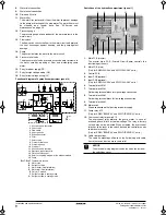
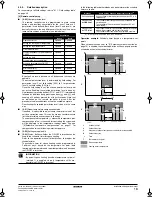
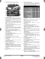
Location of the dip switches, LEDs and buttons
LED state
Throughout the manual the state of the LEDs is indicated as follows:
Function of the push button switch which is located on the outdoor
unit PCB (A1P):
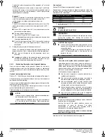
Setting the mode
The set mode can be changed with the
BS1 MODE
button according
to the following procedure:
Press the
BS1 MODE
button for 5 seconds, untill the H1P LED is
on
w
.
Setting procedure
1
Push the
BS2 SET
button according to the required function
(A~E). The LED indication that matches the required function is
shown below in the field marked
:
2
When the
BS3 RETURN
button is pushed, the current setting is
defined.
3
Push the
BS2 SET
button according to the required setting
possibility as shown below in the field marked
.
3.1
Possible settings for function A and E are
ON
(ON) or
OFF
(OFF).
3.2
Possible settings for function B
The noise of level 3 < level 2 < level 1 (
).
3.3
Possible settings for function C and D
For function C
(
L.N.O.P.
)
only: the noise of level 3 < level 2
< level 1 (
).
For function D
(
DEMAND
)
only: the power consumption of
level 1< level 2 < level 3 (
).
4
Push the
BS3 RETURN
button and the setting is defined.
5
When the
BS3 RETURN
button is pushed again, the operation
starts according to the setting.
Refer to the service manual for more details and for other settings.
1
LED H1P~H8P
2
Push button switches
BS1~BS5
x
OFF
w
ON
c
Blinking
BS1 MODE
For changing the set mode
BS2 SET
For field setting
BS3 RETURN
For field setting
BS4 TEST
This push button has no function
BS5 RESET
This push button has no function
LED display
(Default status
before delivery)
Micro-
computer
operation
monitor
Mode
Ready/
Error
Cooling/Heating
changeover
Low
noise
Demand
Multi
Indivi-
dual
Bulk
(master)
Bulk
(slave)
HAP
H1P
H2P
H3P
H4P
H5P
H6P
H7P
H8P
Single system
(a)
(a) EWA/YQ016~032 units are single system units,
EWA/YQ040~064 units are multiple system units
c
x
x
w
x
x
x
x
x
Multiple
system
(a)
Left unit
c
x
x
w
x
x
x
x
w
Right
unit
c
x
x
x
x
x
x
x
c
INFORMATION
If you get confused in the middle of the setting process,
push the
BS1 MODE
button. Then it returns to setting
mode 1 (H1P LED is off).
1
2
BS2
SET
BS1
MODE
BS3
RETURN
BS4
TEST
BS5
RESET
H1P
H2P
H3P
H4P
H5P
H6P
H7P
MODE
TEST:
HWL:
IND
MASTER
SLAVE
L.N.O.P DEMAND
C/H SELECT
H8P
MULTI
Possible functions
A
setting of high static pressure.
B
automatic low noise operation setting at nighttime.
C
low noise operation level setting (
L.N.O.P.
) via the external control
adapter.
D
power consumption limitation setting (
DEMAND
) via the external
control adapter.
E
enabling function of the low noise operation level setting
(
L.N.O.P.
) and/or power consumption limitation setting
(
DEMAND
) via the external control adapter (DTA104A62).
H1P
H2P
H3P
H4P
H5P
H6P
H7P
A
w x w x
x w x
B
w x w x w w x
C
w x w w x
x w
D
w x w w w w x
E
w x
x w w x
x
H1P
H2P
H3P
H4P
H5P
H6P
H7P
ON
w x
x
x
x c x
OFF
(a)
(a) This setting = factory setting
w x
x
x
x
x c
H1P
H2P
H3P
H4P
H5P
H6P
H7P
OFF
(a)
(a) This setting = factory setting
w x
x
x
x
x
x
w x
x
x
x
x c
w x
x
x
x c x
w x
x
x
x c c
H1P
H2P
H3P
H4P
H5P
H6P
H7P
w x
x
x
x
x c
(a)
(a) This setting = factory setting
w x
x
x
x c x
w x
x
x c x
x
1
1
2
3
1
3
1
2
3
4PWEN70082-1C.book Page 16 Wednesday, September 25, 2013 7:31 AM
Содержание EWAQ016BAW
Страница 47: ......
Страница 48: ...4PW70082 1C 2013 07 Copyright 2011 Daikin...


