


Installation and operation manual
13
EWAQ016~ EWYQ016~064BAW
Packaged air-cooled water chiller
4PW70082-1C – 2013.07
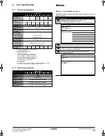
4.6.2.
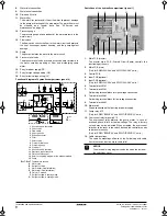
Internal wiring – Parts table – Hydro module
Refer to the wiring diagram sticker on the hydro module front panel 1
(refer to "4.2.2. Opening the unit" on page 7). The abbreviations used
are listed below:
A1P ........................Main PCB (master)
A2P ........................remote controller PCB
A3P ........................Control PCB
A4P ........................Demand PCB (optional)
A5P ........................Main PCB (slave)
A6P ........................Demand PCB (optional)
A7P ........................Remote controller PCB (optional)
C1~C3 ....................Filter capacitor
E1H ........................Switch box heater
E2H ........................Plate heat exchanger heater (PHE1)
E3H ........................Plate heat exchanger heater (PHE2)
E4H ........................Water piping heater
E5H ........................Expansion vessel heater
F1,F2......................Fuse (F, 5 A, 250 V)
F1U (A*P)...............Fuse (T, 3.15 A, 250 V)
HAP........................PCB LED
K11E ......................Electronic expansion valve (PHE1)
K21E ......................Electronic expansion valve (PHE2)
K1P ........................Pump contactor
K1S ........................Pump overcurrent relay
K*R (A3P)...............PCB relay
M1P........................Pump
PS (A*P).................Switching power supply
Q1DI.......................Earth leakage circuit breaker (field supply)
Q1T ........................Thermostat for expansion vessel heater
R11T ......................Leaving water thermistor (PHE1)
R12T ......................Returning water thermistor (PHE1)
R13T ......................Refrigerant liquid thermistor (PHE1)
R14T ......................Refrigerant gas thermistor (PHE1)
R21T ......................Leaving water thermistor (PHE2)
R22T ......................Returning water thermistor (PHE2)
R23T ......................Refrigerant liquid thermistor (PHE2)
R24T ......................Refrigerant gas thermistor (PHE2)
S1F.........................Flow switch (PHE1)
S2F.........................Flow switch (PHE2)
S1M........................Main switch
S1S ........................Thermostat ON/OFF input (field supply)
S2S ........................Thermostat cooling/heating selection
(field supply)
S3S ........................Operation ON input (field supply)
S4S ........................Operation OFF input (field supply)
SS1 (A1P,A5P) .......Selector switch (emergency)
SS1 (A2P) ..............Selector switch (master/slave)
SS1 (A7P) ..............Selector switch (master/slave) (optional)
V1C,V2C ................Ferrite core noise filter
X1M~X4M ..............Terminal strip
X801M (A*P) ..........PCB terminal strip (optional)
Z1F,Z2F (A*P) ........Noise filter
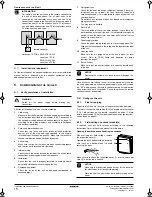
4.6.3.
Installing the main switch handle
Open panel 1 (refer to "4.2.2. Opening the unit" on page 7) and
mount the main switch handle parts as shown below. The handle of
the main switch is mounted on panel 1.
■
For EWA/YQ016~032 refer to figure 10.
A
Panel 1 (refer to "4.2.2. Opening the unit" on page 7)
■
For EWA/YQ040~064 refer to figure 14.
A
Panel 1 (refer to "4.2.2. Opening the unit" on page 7)
4.6.4.
System overview of field wiring
Field wiring consists out of power supply (always including earth) and
communication (=transmission) wiring.
■
Most field wiring on the unit is to be made on the terminal blocks
inside the switch boxes. To gain access to the terminal blocks,
remove switch box service panel. Refer to the instructions
described in "4.2.2. Opening the unit" on page 7 how to remove
this panel and gain access to the inside of the switch box.
■
Cable tie mountings are provided at the wiring entries of the
switch box. See "4.4.2. Main components of the hydro module"
on page 8.
4.6.5.
Connection of the unit power supply and
communication cable(s)
The power supply must be protected with the required safety devices,
i.e. a main switch, a slow blow fuse on each phase and an earth
leakage protector in accordance with the applicable legislation.
Cable requirements
NOTICE
When the main switch is in OFF position, it is possible
to lock the main switch using a suitable padlock.
Refer to figure 13.
Keep in mind that in this case the padlock needs to be
opened and removed before it is possible to turn the
main switch to the ON position.
INFORMATION
■
The electrical wiring diagram can be found on the
inside of the switch box cover.
■
Install the unit, power supply cable and
communication cables at least 1 meter away from
televisions or radios to prevent image interference or
noise.
(Depending on the radio waves, a distance of 1 meter
may not be sufficient to eliminate the noise.)
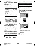
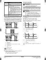
NOTICE
Selection and sizing of the wiring should be done in
accordance with the applicable legislation based on the
information mentioned in the table below:
Item
Cable
bundle Description
Required
number of
conductors
Maximum
running
current
1
PS
Power supply
4+GND
(b)
(b) Refer to the nameplate on the unit or to the technical data book.
2
LV
Standard remote controller (F1/F2)
2
(c)
(c) Minimum cable section 0.75 mm
2
.
3
LV
Secondary remote controller
(P1/P2)
(a)
(a) Optional
2
(c)
4
LV
Thermostat ON/OFF signal
(a)
2
(c)
5
LV
Thermostat cooling/heating signal
(a)
2
(c)
6
LV
Operation ON signal
(a)
2
(c)
7
LV
Operation OFF signal
(a)
2
(c)
8
HV
Cooling/heating output
2
0.3 A
9
HV
Operation ON/OFF output
2
0.3 A
10
HV
Error output
2
0.3 A
11
HV
Water piping heater output
2
1 A
12
HV
Pump ON/OFF output
2
0.3 A
(d)
(d) Only for models without pump (EWAQ*BAW(P/H)* and EWYQ*BAW(P/H)* units.)
.
PS = Power supply (see "4.6.6. Routing" on page 14)
LV = Low voltage (see "4.6.6. Routing" on page 14)
HV = High voltage (see "4.6.6. Routing" on page 14)
4PWEN70082-1C.book Page 13 Wednesday, September 25, 2013 7:31 AM
Содержание EWAQ016BAW
Страница 47: ......
Страница 48: ...4PW70082 1C 2013 07 Copyright 2011 Daikin...