background image

ESIE98–06A

General Outline

Part 1 – System Outline

1–11

3

1

4

5

1

EUWY5-30HB/C

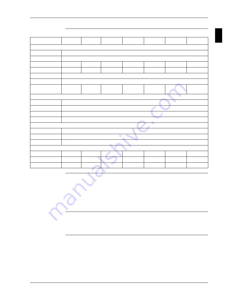
In the following table you will find the electrical specifications of chiller types EUWY5-30HB/C:

Nominal conditions

The nominal conditions are as follows:

entering/leaving chilled water temperature 12/7 °C, ambient air temperature 35 °C

entering/leaving condenser water temperature 45/50 °C; ambient 7 °CDB/6 °CWB

power input is total input:
comp control circuit

sound pressure level is measured at a height of 1.5 m and a distance of 1 m in front of the unit.

Operation range

The operation range contains:

a leaving evaporator water temperature from 4 °C till 20 °C (pull-down condition till 25 °C)

a leaving condenser water temperature from 35 °C till 55 °C.

Model

EUWY5HB

EUWY8HB

EUWY10HB

EUWY15HC

EUWY20HC

EUWY25HC

EUWY30HC

Compressor

phase

3~

Voltage

220 - 380 V

starting current

49 A

79 A

109 A

49 A/109 A

109 A

49 A/109 A

109 A

max. running current

10 A

18 A

21 A

21 A+10 A

2x21 A

2x21 A+10 A

3x21 A

starting method

direct on line

voltage

400 V

nominal running current

5.5 A

9.7 A

12.5 A

5.5 A+12.5 A

2x12.5 A

2x12.5 A+

5.5 A

3x12.5 A

Nominal distribution system voltage

phase

3N~

frequency

50 Hz

voltage

400 V

voltage tolerance

±10 V

Control circuit

phase

1~

recommended fuses

factory installed

voltage

230 V

Unit

nominal running current

8 A

13.2 A

16 A

23 A

31 A

38 A

46 A

recommended fuses

3 x 20 aM

3 x 25 aM

3 x 32 aM

3 x 40 aM

3 x 50 aM

3 x 63 aM

3 x 80 aM

max. running current

12.5 A

21.5 A

24.5 A

36 A

48 A

59.5 A

71.5 A

Содержание EUWA/Y5-30HB/C(Z)

Страница 1: ...IRCUIT SECONDARY WATER CIRCUIT CHILLER PRIMARY WATER CIRCUIT PRIMARY WATER CIRCUIT C C H H 4 3 7 7 5 6 1 2 16 10 11 11 14 15 13 9 9 8 12 ESIE98 06A Service Manual EUWA Y5 30HB C Z Small air cooled wat...

Страница 2: ......

Страница 3: ...at Is in This Chapter 1 21 2 2 Functional Diagram Refrigeration Circuit for EUWA5 30HB C Z 1 22 2 3 Main Parts Refrigeration Circuit for EUWA5 30HB C Z 1 24 2 4 Functional Diagram Refrigeration Circui...

Страница 4: ...Cool Heat and Temperature Setting 2 18 2 4 What Happens in Case of an Alarm or a Warning 2 20 2 5 Settings Direct and User Parameters 2 21 2 6 How to Read or Adjust Parameter Settings the Programming...

Страница 5: ...Z 3 10 2 4 Safeties Overview 3 12 3 Checking the Inputs and Outputs 3 1 What Is in This Chapter 3 13 3 2 Checking the Temperature Sensors 3 14 3 3 Checking the Digital Inputs and Outputs 3 17 3 4 Che...

Страница 6: ...1 4 5 Part 4 Commissioning and Test Run 4 1 1 Pre Test Run Checks 1 1 What Is in This Chapter 4 3 1 2 General Checks 4 4 1 3 Water Piping Checks 4 5 1 4 Electrical Checks 4 7 2 Test Run Operation Dat...

Страница 7: ...sult the check lists in Pre Test Run Checks on page 4 3 Two controllers The digital controller for chiller types EUWA Y5 10HB Z differs from the digital controller for chiller types EUWA Y15 30HC Z Us...

Страница 8: ...Introduction ESIE98 06A vi 3 1 4 5...

Страница 9: ...e EUWA Y5 30HB C Z chiller types Once all the elements of the installation are briefly described and the installation set up is understood a functional description of all elements will be given in the...

Страница 10: ...ESIE98 06A 1 2 Part 1 System Outline 3 1 1 4 5...

Страница 11: ...apter Introduction In this chapter you will find the outlook drawing and the installation outline of the water chillers EUWA Y5 30HB C Z Overview This chapter covers the following topics Topic See pag...

Страница 12: ...B51 30H CB51 50H CB51 60H CB51 60H CB51 30H 2xCB51 60H 2xCB51 60H CB51 30H 3xCB51 60H water flow rate Min 17 l min Max 75 l min Min 30 l min Max 120 l min Min 40 l min Max 145 l min Min 50 l min Max 2...

Страница 13: ...ondition till 25 C refrigerant charge 3 6 kg 5 1 kg 5 9 kg 5 9 3 6 kg 2x5 9 kg 2x5 9 3 6 kg 3x5 9 kg refrigerant control capillary tube oil type SUNISO 4GSDID K Dimensions h x w x d 1444 x 645 x 700 m...

Страница 14: ...stem 1 114 l 171 l 243 l 490 l 490 l 700 l 975 l water flow rate Min 17 l min Max 75 l min Min 30 l min Max 120 l min Min 40 l min Max 145 l min Min 60 l min Max 220 l min Min 80 l min Max 290 l min M...

Страница 15: ...ondenser water temperature from 35 C till 55 C refrigerant charge 3 6 kg 5 1 kg 5 9 kg 5 9 3 6 kg 2x5 9 kg 2x5 9 3 6 kg 3x5 9 kg refrigerant control capillary tube oil type SUNISO 4GSDID K oil charge...

Страница 16: ...em 1 120 l 210 l 250 l 500 l 500 l 740 l 1000 l water flow rate Min 18 l min Max 60 l min Min 30 l min Max 100 l min Min 38 l min Max 120 l min Min 56 l min Max 180 l min Min 76 l min Max 240 l min Mi...

Страница 17: ...FVC68D FVC68D FVC68D FVC68D oil charge volume 1 5 l 2 7 l 2 7 l 2 7 1 5 l 2x2 7 l 2x2 7 1 5 l 3x2 7 l n of circuits 1 1 1 2 2 3 3 Dimensions h x w x d 1444 x 645 x 700 mm 1220 x 1290x 700 mm 1444 x129...

Страница 18: ...rting current 49 A 88 A 79 A 142 A 109 A 183 A 49 A 88 A 109 A 183 A 109 A 183 A 49 A 88 A 109 A 183 A 109 A 183 A max running cur rent 10 A 17 A 18 A 28 A 21 A 34 A 10 A 17 A 21 A 34 A 2x21 A 34 A 2x...

Страница 19: ...n condition till 25 C a leaving condenser water temperature from 35 C till 55 C Model EUWY5HB EUWY8HB EUWY10HB EUWY15HC EUWY20HC EUWY25HC EUWY30HC Compressor phase 3 Voltage 220 380 V starting current...

Страница 20: ...1 A 34 A 10 A 17 A 21 A 34 A 2x21 A 34 A 2x21 A 34 A 10 A 17 A 3x21 A 34 A starting method direct on line voltage 400 V 230 V nominal running current 6 6 A 11 4 A 10 4 A 18 A 13 1 A 22 8 A 6 6 A 11 4...

Страница 21: ...oduction Below you will find the outlook drawings of the EUWA Y5 30HB C Z chiller types The diagrams indicate the following important items dimensions service space main components location operation...

Страница 22: ...General Outline ESIE98 06A 1 14 Part 1 System Outline 3 1 1 4 5 EUWA Y8HB Z The figure below displays the outlook of the chiller types EUWA Y8HB Z...

Страница 23: ...ESIE98 06A General Outline Part 1 System Outline 1 15 3 1 4 5 1 EUWA Y10HB Z The figure below displays the outlook of the chiller types EUWA Y10HB Z...

Страница 24: ...General Outline ESIE98 06A 1 16 Part 1 System Outline 3 1 1 4 5 EUWA Y15HC Z The figure below displays the outlook of the chiller types EUWA Y15HC Z...

Страница 25: ...ESIE98 06A General Outline Part 1 System Outline 1 17 3 1 4 5 1 EUWA Y20HC Z The figure below displays the outlook of the chiller types EUWA Y20HC Z...

Страница 26: ...General Outline ESIE98 06A 1 18 Part 1 System Outline 3 1 1 4 5 EUWA Y25HC Z The figure below displays the outlook of the chiller types EUWA Y25HC Z...

Страница 27: ...ESIE98 06A General Outline Part 1 System Outline 1 19 3 1 4 5 1 EUWA Y30HC Z The figure below displays the outlook of the chiller types EUWA Y30HC Z...

Страница 28: ...General Outline ESIE98 06A 1 20 Part 1 System Outline 3 1 1 4 5...

Страница 29: ...e and is therefore not described Overview This chapter covers the following topics Topic See page 2 2 Functional Diagram Refrigeration Circuit for EUWA5 30HB C Z page 1 22 2 3 Main Parts Refrigeration...

Страница 30: ...onal Diagram Refrigeration Circuit for EUWA5 30HB C Z Functional diagram EUWA5 30HB C The figure below displays the functional diagram of the refrigeration circuit of the chiller types EUWA5 30HB C Th...

Страница 31: ...functional diagram of the refrigeration circuit of the chiller types EUWA5 30HB C Z with or without glycol application The numbers on the drawing refer to the numbers in the table on page 1 24 MC EUWA...

Страница 32: ...heat exchanger is of the brazed plate heat exchanger type 5 Capillary tubes Used for R 22 models EUWA5 30H Expansion valve Used for R 407C models EUWA5 30HZ 6 High pressure switch The setting is 28 ba...

Страница 33: ...C The figure below displays the functional diagram of the refrigeration circuit of the chiller types EUWY5 30HB C The numbers on the drawing refer to the numbers in the table on page 1 27 SHP MC YRV...

Страница 34: ...Functional diagram EUWA5 30HB C glycol application The figure below displays the functional diagram of the refrigeration circuit of the chiller types EUWA5 30HB C with glycol application The numbers...

Страница 35: ...pe BSP The pipes are not insulated for EUWY5 30H and are insulated for EUWA5 30H Z with glycol application If Copper field piping is used for the water circuit then pre caution should be taken for ele...

Страница 36: ...Piping Layout ESIE98 06A 1 28 Part 1 System Outline 3 1 1 4 5...

Страница 37: ...his chapter is to guide you through the PCBs and the wiring diagrams Therefore we use schematic drawings and wiring diagrams which indicate and locate the necessary information Overview This chapter c...

Страница 38: ...circuit of the chiller types EUWA Y5 10HB Z Power Supply MCHRTF fan control G0 B1 B2 B3 ID5 ID3 ID1 comp line X2 X1 line heatertape 4 way valve amb probe outlet probe inlet probe Evaporator thermostat...

Страница 39: ...ct ID2 GND S7S remote cool heat ID3 GND K11 Q1D K4S HP discharge temperature overcurrent ID4 GND S16T evaporator thermostat ID5 GND S9S remote ON OFF B1 GND R3T sensor inlet water B2 GND R4T sensor ou...

Страница 40: ...Y15 30HC Z G G0 VG0 VG1 Y1 Y0 ID11R ID11 ID12R ID12 NO11 C11 NC11 NO10 C10 NC10 NO9 C9 NC9 NO8 C8 NO7 C7 NO6 C6 NO13 C13 B8 24Vcc B7 B6 AVSS B5 B4 AVSS B3 B2 AVSS B1 IDCM2 ID10 ID9 ID8 ID7 ID6 IDCM1 I...

Страница 41: ...3 K3A auxiliary relay for safety circuit 3 ID4 S7S field wiring switch for remote cool heat selection ID5 S10L S11L field wiring flow switch pump contact J5 C1 NO1 K1M compressor contactor circuit 1 C...

Страница 42: ...g diagrams of the following chiller types are displayed on the pages below Chiller type See page EUWA5 8 10HB page 1 35 EUWY5 8 10HB page 1 36 EUWA5 8 10HBZ page 1 37 EUWA15 20HC page 1 38 EUWY15 20HC...

Страница 43: ...r switch contact that closes if pump is working flowswitch switch for remote start stop high pressure switch ambient temperature sensor outlet water temperature sensor inlet water temperature sensor r...

Страница 44: ...r temperature sensor inlet water temperature sensor reverse phase protector thermal protector fan discharge thermal protector main earth terminal compressor motor fan motors auxiliary relay pumpcontac...

Страница 45: ...sensor inlet water temperature sensor reverse phase protector thermal protector fan discharge thermal protector main earth terminal compressor motor fan motors auxiliary relay pumpcontactor contactor...

Страница 46: ...mperature measurement outlet water temperature sensor sensor for evaporator condensor inlet water t d measurement reverse phase protector thermal protector fan 1 2 discharge thermal protector circuit1...

Страница 47: ...closes if pump is working flowswitch switch for remote start stop high pressure switch for circuit1 circuit2 sensor for ambient temperature measurement outlet water temperature sensor sensorforevapor...

Страница 48: ...poratorheatertape S25T thermostatforliquidinjectioncircuit1 circuit2 S19T S20T evaporatingtemperaturethermostatcircuit1 circuit2 S16T S17T mainisolatorswitch S12S contactthatclosesifpumpisworking S11L...

Страница 49: ...wswitch switchforremotestart stop highpressureswitchforcircuit1 circuit2 circuit3 sensorforambienttemperaturemeasurement outletwatertemperaturesensor sensorforevaporator condensorinletwatert dmeasurem...

Страница 50: ...switchforremotestart stop highpressureswitchforcircuit1 circuit2 circuit3 sensorforambienttemperaturemeasurement outletwatertemperaturesensor sensorforevaporator condensorinletwatert dmeasurement reve...

Страница 51: ...temperature measurement outlet water temperature sensor sensor for evaporator condensor inlet water t d measurement reverse phase protector thermal protector fan 1 2 discharge thermal protector circui...

Страница 52: ...ESIE98 06A Wiring Layout Part 1 System Outline 1 44...

Страница 53: ...ulted in the Input Output Menu on page 2 39 Item Code s contact Description EUWA5 10HB Z EUWY5 10HB EUWA15 20HC Z EUWY15 20HC EUWA25 30HC Z EUWY25 30HC Remark 1 L1 L2 L3 N PE power supply to unit X X...

Страница 54: ...to unit L1 L2 L3 N PE 2 S12S mains isolator L1 L2 L3 N PE 3 S7S remote cool heat setting 78 79 5 S9S remote start stop 77 76 6 S10L S11L flow switch pump contact 77 75 7 KP pump contactor output 73 7...

Страница 55: ...pump contact 72 76 7 KP pump contactor output 77 78 8 H1P remote alarm indication 79 80 9 H2P general operation indication 81 82 10 H3P circuit 1 operation indication 83 84 11 H4P circuit 2 operation...

Страница 56: ...p contactor output 77 78 8 H1P remote alarm indication 79 80 9 H2P general operation indication 81 82 10 H3P circuit 1 operation indication 83 84 11 H4P circuit 2 operation indication 85 86 12 H5P cir...

Страница 57: ...oubleshooting An extensive overview of the functioning of the controllers is also given in this part Knowledge of the controllers is indispensable to gain valuable information prior to servicing and t...

Страница 58: ...ESIE98 06A 2 2 Part 2 Functional Description 3 1 2 4 5...

Страница 59: ...tal when diagnosing a malfunction which is related to the functional control Overview This chapter covers the following topics Topic See page 1 2 Operation Range page 2 4 1 3 Operation Flowchart page...

Страница 60: ...nd in heating mode with R 22 38 43 4 16 25 0 15 5 36 0 5 10 ZL ZH Glycol Water Standard outdoor temperature C leaving water temperature C standard option Range for pull down operation Protect the wate...

Страница 61: ...ure C leaving water temperature C standard option Range for pull down operation Protect the water circuit against freezing for EUWA8 10HBZ If the units operate below 5 C and are installed in a rather...

Страница 62: ...C Z The operation of chiller types EUWA5 30HB Z is clarified in the schematic diagram below EUWY5 30HB C The operation of chiller types EUWY5 30HB is clarified in the schematic diagram below Power on...

Страница 63: ...tarts The minimum time interval between two defrost cycli is 20 minutes Start condition detail for EUWY15 30HC The relation between the coil sensor temperature and the ambient temperature for chiller...

Страница 64: ...op defrost start defrost stop defrost Tcoil 10 C Tcoil 0 6xTamb 10 3 Tcoil 10 C 150 s timer 1 20 min timer 3 10 min timer 2 10 min and stopped timer 2 150 s timer 1 Display EUWY5 10HB d1 Display EUWY1...

Страница 65: ...llowing picture shows the layout of the defrost PCB An overview of the inputs and outputs of the defrost PCB is given in Defrost PCB on page 3 6 C D T1 T2 A 3 3 B CN 1 CN 2 green LED C P U defrost swi...

Страница 66: ...ircuit layout The following table gives information concerning the horsepower per circuit Defrost possibilities The first column in the following table shows the circuits that are in defrost The other...

Страница 67: ...Screen 3 of the user settings menu provides the ability to modify the thermostat parameters c cooling set point d heating set point c d compressor ON OFF inlet water temperature Description Lower lim...

Страница 68: ...2 fans steps for EUWA5 10HB in cooling mode Fansteps incooling mode with option EKHP8 10K Head pressure control enables an extra fan step when the EKHP8 10K kit for operation range down to 15 C optio...

Страница 69: ...re control as part of the standardized switch box For the EUWY head pressure control is not used to its full extend while its operation range is limited to 15 C In the wiring diagram this head pressur...

Страница 70: ...ze up protection to control the evaporating temperature The following table shows all the characteristics of soft and hard freeze up protection 1 Alarm is on hold and reset goes automatically Characte...

Страница 71: ...arn to work with the controller for the chiller types EUWA Y5 10HB Z Overview This chapter covers the following topics Topic See page 2 2 The EUWA Y5 10HB Z Controller page 2 16 2 3 Start Stop Cool He...

Страница 72: ...l list of parameters press for 5 s to save a parameter modification to return to normal operation m to deactivate the buzzer in case of an alarm u to scroll up through the list of direct user paramete...

Страница 73: ...wering the unit note 1 pv d the unit EEPROM is copied into the key after pressing both keys and then powering the unit note 1 Key Function LED Function the compressor is inactive the compressor can no...

Страница 74: ...re setting Use the u and d keys to adjust the water temperature If start stop set up and cool heat set up then to local H7 0 local H6 0 press c for 5 seconds start stop in cooling mode Always stop the...

Страница 75: ...unit on the following happens Stage Description 1 The o LED starts blinking indicating that the initialization cycle is started The c LED or the h LED lights up indicating whether cooling or heating m...

Страница 76: ...case of an alarm refer to What to do in the event of an alarm on page 3 11 Alarm Warning Function Protects the unit Gives additional service information Description the unit is shut down the buzzer i...

Страница 77: ...it values Step value measurement unit C or F user d 0 C 0 or 1 1 cooling temperature set point direct r1 12 0 C 7 0 C to 25 0 C 0 1 C cooling temperature difference direct r2 3 0 C 0 3 C to 19 C 0 1 C...

Страница 78: ...ct and user parameters parameters can be displayed but not modified Selecting cooling or heating mode Resetting the timers c9 and cv can be resetted For information about how to change a parameter ref...

Страница 79: ...uttons untouched for 1 minute The modifications will not be saved Do you want access to all parameters BEGIN Enter the user password 22 with the u and d keys Press s Select the parameter using the u a...

Страница 80: ...The Controller for the EUWA Y5 10HB Z Chillers ESIE98 06A 2 24 Part 2 Functional Description 3 1 2 4 5...

Страница 81: ...topics Topic See page 3 2 The EUWA Y15 30HC Z Controller page 2 26 3 3 Start Stop Cool Heat and Temperature Setting page 2 27 3 4 What Happens in Case of an Alarm page 2 28 3 5 Menu Overview page 2 2...

Страница 82: ...er there is a previous or next screen An overview is given below Screen detail Each screen contains 4 lines which give information about a setting a description and an entry field The entry fields can...

Страница 83: ...ing before the remote start stop is active If the remote start stop is not enabled then the LED f is off How to cool or heat To change from cooling to heating or vice versa press d If cooling operatio...

Страница 84: ...al circuits Description All compressors are shut down The red LED inside the g key lights up The buzzer is activated The compressor of the corresponding circuit is shut down The red LED inside the g k...

Страница 85: ...of the compressor timers page 2 36 t History direct Screen 1 To read the unit safety information after a shutdown page 2 37 Screen 2 To read the safety information of circuit 1 after a shutdown page...

Страница 86: ...nu key Does the controller prompt you to give the password Enter the password using the h key Refer to page 2 41 Press the j key Select the desired screen using the h key Do you want to adjust a param...

Страница 87: ...ctual inlet water temperature 3 AMBIENT actual ambient temperature 4 THERM STEP actual thermostat step Line n Display Description 1 OUTLET WATER TEMP screen title 2 4 OUTL WATER 1 2 3 actual outlet wa...

Страница 88: ...re is no outlet water control available in these units Selection between set point 1 and 2 You can select set point 1 or 2 by the remote dual set point switch if installed refer Field Wiring on page 1...

Страница 89: ...control page 2 33 2 MANUAL SETINGS To adjust and activate manual control mode page 2 33 3 THERM SETINGS To adjust the thermostat settings page 2 34 4 BMS SETTINGS To adjust the BMS settings page 2 34...

Страница 90: ...s the ability to assign password protection to the set points menu Line n Display Description Lower limit Upper limit Step Default 1 THERM SETTINGS screen title 2 STEPS number of thermo stat steps 1 3...

Страница 91: ...measurement probe To adjust the settings use the programming procedure on page 2 30 Line n Display Description Lower limit Upper limit Step Default 1 SENSOR ACCURACY screen title 2 INLET WATER SENSOR...

Страница 92: ...r default 15 s 3 FLOWSTOP Delay timer that starts counting when the water flow through the evaporator stops during normal operation if the water flow has not restarted during the countdown the unit wi...

Страница 93: ...eens 2 4 These screens show the circuit history Line n Display Description 1 UNIT HISTORY XXX x the total number of unit shutdowns 2 REVERSE PHASE PROT FLOW HAS STOPPED the unit safety reverse phase p...

Страница 94: ...o screens Screen 1 This screen shows the unit information Screen 2 This screen shows extra unit information Line n Display Description 1 UNIT INFORMATION screen title 2 UNITNAME the unit name 3 REFRIG...

Страница 95: ...nd the reverse phase protector Screen 5 This screen shows the status of the compressors Line n Display Description 1 DIGITAL INPUTS screen title 2 4 SAFETY 1 2 3 indicates whether a safety of circuit...

Страница 96: ...n Display Description and status 1 RELAY OUTPUTS screen title 2 4 LPBYPASS 1 2 3 low pressure bypass switch of circuit 1 2 or 3 active or not active Line n Display Description and status 1 RELAY OUTP...

Страница 97: ...al factory password is 1914 To reset a pre defined user password press j and q simultaneously for 5 seconds Screen Using this menu you can change the password How to change the password To change the...

Страница 98: ...The Controller for the EUWA Y15 30HC Z Chillers ESIE98 06A 2 42 Part 2 Functional Description 3 1 2 4 5...

Страница 99: ...ut signals If the unit is not performing properly first check the input devices then the PCBs and finally the output devices The chapters in this part are arranged according to this sequence What is i...

Страница 100: ...ESIE98 06A 3 2 Part 3 Troubleshooting 3 1 3 4 5...

Страница 101: ...heck the inputs and outputs In this chapter an overview is given The PCB for the chiller types EUWA Y5 10HB Z differs from the PCB for the chiller types EUWA Y15 30HC Z Therefore the overview has been...

Страница 102: ...sensor R4T X1 B2 GND e2 r6 outlet water temperature sensor R5T X1 B3 GND e3 r8 coil temperature sensor digital input transducer R1P X1 ALL h1 fl reverse phase protector S11L S10L X1 ID1 GND h1 flow sw...

Страница 103: ...4 switch for remote cool heat selection S8S field contacts J3 ID9 switch for dual set point S9S field contacts J3 ID10 switch for remote start stop S10L field contact J4 ID5 flow switch S11L field con...

Страница 104: ...uit Control on page 2 9 Type Detail Wiring diagram symbol Wiring connection terminal Description analog input sensor R11T S13DF CN1 sensor for coil temperature measurement circuit 1 R12T S13DF CN2 sen...

Страница 105: ...duction In the first stage of the troubleshooting sequence it is important to interpret the fault indication on the controller display This will help you to find the cause of the problem Overview This...

Страница 106: ...EEPROM on the controller PCB inside the unit is defective alarm automatic page 1 30 fl No water flow either during the period of 15 seconds after the pump was started or for 5 seconds while the compr...

Страница 107: ...m The buzzer stops 2 Find the cause of the alarm and correct it The system is repaired 3 Reset the alarm manually by pressing the u and d key simultaneously for approximately 5 seconds The controller...

Страница 108: ...individual circuits Description all compressors are shut down the red LED inside the g key lights up the buzzer is activated the compressor of the corresponding circuit is shut down the red LED inside...

Страница 109: ...s of a circuit are connected in series 2 Press the j key if you want to consult the opera tion parameters The following screen is displayed TEMPERATURE LIMITS OUTL WATER INLET WATER AMB TEMP After 20...

Страница 110: ...ct faze sequence switch power back on R1P K4A contact on off high pressure switch h1 safety 1 2 3 active discharge pres sure 28 bar manual software reset S1PH S2PH S3PH switch on off contact leaving e...

Страница 111: ...This Chapter Introduction In this chapter you will find information on how to measure and check the most important inputs Overview This chapter covers the following topics Topic See page 3 2 Checking...

Страница 112: ...R5T R6T sensors connected to the defrost PCB R11T R12T R21T R22T R31T R32T How to check To check the temperature sensors proceed as follows Table 1 In table 1 you will find the temperature resistance...

Страница 113: ...1 92 1 87 1 82 29 109 30 105 70 102 20 22 11 32 11 20 11 07 77 1 86 1 81 1 78 28 103 80 100 40 97 16 23 10 90 10 78 10 60 78 1 81 1 76 1 71 27 98 63 95 47 92 41 24 10 49 10 38 10 27 79 1 76 1 71 1 68...

Страница 114: ...0 111 99 108 96 25 20 00 19 56 60 4 96 4 87 9 106 03 103 18 26 19 14 18 73 61 4 97 4 70 8 100 41 97 73 27 18 32 17 93 62 4 62 4 54 7 95 14 92 61 28 17 54 17 17 63 4 46 4 38 6 90 17 87 79 29 16 80 16 4...

Страница 115: ...it of the unit If however the latter is the case then you should measure the relevant signals using the schematic input route shown above Output route The output is generated from the PCB If a device...

Страница 116: ...it Wiring code Type voltage Fuse code main supply L1 L2 L3 M 3 phases 200 V AC F1U F2U F3U control circuit fans relays L2 M 1 phase 230 V AC F7B control circuit pcb s TR1 prim 1 phase 230 V AC F5B TR1...

Страница 117: ...trical circuit repair are explained Not all repair procedures are described Some procedures are considered common practice Overview This chapter covers the following topics Topic See page 4 2 Items to...

Страница 118: ...rrect if set up incorrectly Check the field wiring in case of remote control One of the timers is still active Check the timers overview in this manual or in the controller and wait until all timers h...

Страница 119: ...n outdoor air temperature 43 C leaving condenser water 25 C state of the condenser clean Flow switch or pump contact damaged flow switch incorrect pump operation incorrect field wiring defective contr...

Страница 120: ...ll relevant European and national regulations Step Action 1 Recover the refrigerant from the unit It is strictly forbidden to release refrigerant into the atmosphere during service or repair jobs 2 Pe...

Страница 121: ...hod 1 To unlock the keyboard proceed as follows Unlock the keyboard method 2 A second method to unlock the keyboard is shown in the table below When the unit is the unit stays off off on on Step Actio...

Страница 122: ...e same way as the old controller 4 Reconnect the controller Step Action Result 1 Put on the power supply Make sure that the unit is not working in cooling or heating mode If so press h to switch the u...

Страница 123: ...for cooling speed factory 35 17 0 F6 max temp for cooling speed factory 45 19 2 F7 min temp for heating speed factory 35 50 F8 max temp for heating speed factory 30 48 FA temp necessary to turn off th...

Страница 124: ...factory 0 0 7 offset for 2 factory 0 0 8 offset for 3 factory 0 0 b digital filter factory 4 4 c input limitation factory 8 8 d measurement unit user 0 0 r1 cooling set point direct 12 12 r2 cooling...

Страница 125: ...0 1 PA low pressure alarm when the compressor is OFF factory 0 0 Pb high temperature alarm set user 90 90 PC high temperature alarm delayed at start up user 30 30 H5 pump functional logic factory 1 1...

Страница 126: ...nections of the old PCB 2 Remove the old PCB 3 Place the new PCB in the same way as the old PCB 4 Reconnect the PCB Step Action Result 1 Put on the power supply After a few seconds the user terminal w...

Страница 127: ...EUWA15 1 Use h to select the correct type 2 Press j 2 MANUFACT NR manufacturing number 0000000 1 Use h and j to change the digits 2 Press j 3 REFRIGERANT refrigerant type R 134a 1 Use h to select the...

Страница 128: ...ture shows how to set the dipswitch on the back of the controller for EUWA Y5 10HB Z Setting of dipswitch for EUWA Y15 30HC Z The following picture shows how to set the dipswitch on the back of the co...

Страница 129: ...ube to the compressor tube to the inside coil tube to the outside coil left pilot back capillary tube right pilot back capillary tube coil bleed hole compressor piston needle pilot body piston body Di...

Страница 130: ...the solenoid to loosen the dirt 4 If unsuccessful remove the valve and wash it out Check on air before reinstalling If there is still no movement replace the valve add a new strainer to the discharge...

Страница 131: ...shift replace the valve There is body damage Replace the valve Hot Warm Warm Hot Hot Hot Both parts of pilot are still open To resolve 1 Raise the head pressure 2 Operate the solenoid to free the part...

Страница 132: ...Hot Cool Hot as in column 1 Cool as in column 1 Hot Temperature of valve body There is dirt in one bleed hole To resolve 1 Raise the head pressure 2 Operate the solenoid 3 If unsuccessful remove the...

Страница 133: ...Cool as in column 1 Temperature of valve body Warmer than valve body At the end of the slide the piston needle is leaking To resolve 1 Operate the valve several times 2 Recheck 3 If there is an exces...

Страница 134: ...Troubleshooting ESIE98 06A 3 36 Part 3 Troubleshooting 3 1 3 4 5...

Страница 135: ...This part offers a systematic approach to test run checks and test value which will guarantee a high quality installation and operation of the units It is therefore recommended to read the chapters in...

Страница 136: ...ESIE98 06A 4 2 Part 4 Commissioning and Test Run 3 1 4 5...

Страница 137: ...What Is in This Chapter Introduction As shown in the table below we have grouped the pre test run checks into three main groups to facilitate the servicing Overview This chapter covers the following t...

Страница 138: ...y for the condensed water Only for EUWY5 30HB C 6 it is necessary to place a heatertape inside the drain system to prevent ice accumulation and possible drain blockage during wintertime 7 no metal dus...

Страница 139: ...d 5 measurement points for temperature and pressure are available on the water circuit 6 the flow switch and pump are properly working 7 air purge points are installed on the high parts of the water p...

Страница 140: ...Cw water 4186 J kgK Water quality In the table below you will find the required water quality specifications 0 5 x Q x t V m 2 x x d x Cw Evaporator water Heated water low temperature Tendency if out...

Страница 141: ...viates less than 10 from the nominal value 3 the flow switch and pump contact are properly wired up 4 the optional wiring for pump control is installed 5 the optional wiring for remote start stop is i...

Страница 142: ...Pre Test Run Checks ESIE98 06A 4 8 Part 4 Commissioning and Test Run 3 1 4 5...

Страница 143: ...t Value Suction pressure Cooling 4 8 5 bar Heating 1 5 bar Discharge pressure Cooling 7 22 bar Heating 15 24 bar Maximum water pressure 10 bar Measurement Value Leaving water temperature Cooling 4 20...

Страница 144: ...3 1 4 4 5 Currents Unit Nominal current Maximum current Fuses EUWA Y5HB 8 A 12 5 A 3x20 aM EUWA Y8HB 13 2 A 21 5 A 3x25 aM EUWA Y10HB 16 A 24 5 A 3x32 aM EUWA Y15HC 23 A 36 A 3x40 aM EUWA Y20HC 31 A 4...

Страница 145: ...duct an inspection to make sure that there is no air mixed in the water pipes Even if air is removed at the beginning air can sometimes enter later Therefore bleed the system regularly Check the tight...

Страница 146: ...ESIE98 06A 5 2 Part 5 Maintenance 3 1 5 4...

Страница 147: ...arameters k 2 23 change parameters k 2 30 change password k 2 41 changing of PCB k 3 24 changing of PCB k 3 28 checking digital inputs outputs k 3 17 inputs outputs k 3 13 power supply and fuses k 3 1...

Страница 148: ...2 29 2 32 step difference k 2 11 timers k 2 29 2 36 user settings k 2 29 2 33 controller EUWA Y5 10H Z k 2 15 controller EUWY A15 30H Z k 2 25 cool heat k 2 18 cool heat k 2 27 cooling set point k 2 3...

Страница 149: ...ure control k 2 12 head pressure control k 2 13 heating set point k 2 21 heating set point k 2 32 heating temperature difference k 2 21 high pressure service port k 1 24 1 27 high pressure switch k 1...

Страница 150: ...temperature k 2 21 outlook drawing k 1 13 overview of inputs outputs k 3 3 P parameters access k 2 21 how to change k 2 23 how to change k 2 30 how to read k 2 23 how to read k 2 30 overview k 2 21 pa...

Страница 151: ...k 1 27 refrigeration circuit k 1 22 1 24 1 25 remote control cool heat k 2 21 cool heat k 2 33 start stop k 2 21 start stop k 2 33 remote control k 2 33 remote control k 2 21 remote dual set point sw...

Страница 152: ...settings k 2 11 2 34 stepdifference k 2 11 2 34 steps k 2 11 2 34 STPL k 2 11 2 34 thermostat control k 2 11 thermostat for liquid injection valve k 1 27 thermostat parameters k 2 11 2 34 time delay...

Отзывы: