ESIE98–06A
The Controller for the EUWA/Y15-30HC(Z) Chillers
Part 2 – Functional Description
2–29
3
2
4
5
1
3.5
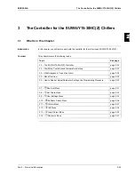
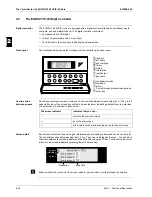
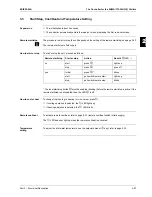
Menu Overview
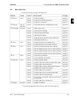
An overview of the menus is given in the table below.
1
: You can assign password protection to the set points menu (see page 2-34)
Menu key
Access
Screen n°
Task description
See page
a
Read-out
direct
Screen 1
To consult the settings.
page 2-31
Screen 2
To consult the outlet water temperature.
page 2-31
Screen 3
To consult the circuits status.
page 2-31
z
Set points
direct or
password
1
Screen 1
To consult and adjust the cooling/heating set points.
page 2-32
e
User settings
password
Screen 1
To select remote control.
page 2-33
Screen 2
To adjust the manual settings.
page 2-33
Screen 3
To adjust the thermostat settings.
page 2-34
Screen 4
To adjust the BMS settings.
page 2-34
Screen 5
To assign password protection to the set points menu
1
.
page 2-34
Screen 6
To adjust the sensor accuracy.
page 2-35
r
Timers
direct
Screen 1
To read the actual value of the general timers.
page 2-36
Screen 2
To read the actual value of the compressor timers.
page 2-36
t
History
direct
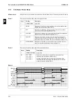
Screen 1
To read the unit safety information after a shutdown.
page 2-37
Screen 2
To read the safety information of circuit 1 (after a shutdown).
page 2-37
Screen 3
To read the safety information of circuit 2 (after a shutdown).
page 2-37
Screen 4
To read the safety information of circuit 3 (after a shutdown).
page 2-37
y
Info
direct
Screen 1
To consult the unit information.
page 2-38
Screen 2
To consult additional unit information.
page 2-38
u
Input/output
direct
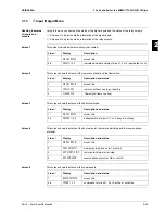
Screen 1
To read the activated safeties.
page 2-39
Screen 2
To read the status of the remote cool/heat and flow switch.
page 2-39
Screen 3
To read the status of the defrost switch.
page 2-39
Screen 4
To read the status of the dual set point switch, the remote
start/stop and the reverse phase protector.
page 2-39
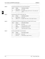
Screen 5
To read the status of the compressors.
page 2-39
Screen 6
To read the status of the low pressure bypass switch.
page 2-40
Screen 7
To read the status of the fan speed relay.
page 2-40
Screen 8
To read the alarm and operation indication and the status of
the pump contact.
page 2-40
Screen 9
To read the status of the reversing valve.
page 2-40
q
Password
password
Screen 1
To change the password.
page 2-41
Содержание EUWA/Y5-30HB/C(Z)
Страница 2: ......
Страница 8: ...Introduction ESIE98 06A vi 3 1 4 5...
Страница 10: ...ESIE98 06A 1 2 Part 1 System Outline 3 1 1 4 5...
Страница 28: ...General Outline ESIE98 06A 1 20 Part 1 System Outline 3 1 1 4 5...
Страница 36: ...Piping Layout ESIE98 06A 1 28 Part 1 System Outline 3 1 1 4 5...
Страница 52: ...ESIE98 06A Wiring Layout Part 1 System Outline 1 44...
Страница 58: ...ESIE98 06A 2 2 Part 2 Functional Description 3 1 2 4 5...
Страница 80: ...The Controller for the EUWA Y5 10HB Z Chillers ESIE98 06A 2 24 Part 2 Functional Description 3 1 2 4 5...
Страница 98: ...The Controller for the EUWA Y15 30HC Z Chillers ESIE98 06A 2 42 Part 2 Functional Description 3 1 2 4 5...
Страница 100: ...ESIE98 06A 3 2 Part 3 Troubleshooting 3 1 3 4 5...
Страница 134: ...Troubleshooting ESIE98 06A 3 36 Part 3 Troubleshooting 3 1 3 4 5...
Страница 136: ...ESIE98 06A 4 2 Part 4 Commissioning and Test Run 3 1 4 5...
Страница 142: ...Pre Test Run Checks ESIE98 06A 4 8 Part 4 Commissioning and Test Run 3 1 4 5...
Страница 146: ...ESIE98 06A 5 2 Part 5 Maintenance 3 1 5 4...


