ESIE98–06A
Wiring Layout
Part 1 – System Outline
1–29
3
1
4
5
1
Part 1
3
Wiring Layout
3.1
What Is in This Chapter
Introduction
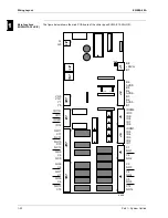
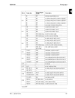
The purpose of this chapter is to guide you through the PCBs and the wiring diagrams. Therefore, we
use schematic drawings and wiring diagrams, which indicate and locate the necessary information.
Overview
This chapter covers the following topics:
Topic
See page
3.2 – Main functions of the chiller
page 1-30
3.3 – Wiring Diagrams
page 1-34
3.4 – Field Wiring
page 1-45
Содержание EUWA/Y5-30HB/C(Z)
Страница 2: ......
Страница 8: ...Introduction ESIE98 06A vi 3 1 4 5...
Страница 10: ...ESIE98 06A 1 2 Part 1 System Outline 3 1 1 4 5...
Страница 28: ...General Outline ESIE98 06A 1 20 Part 1 System Outline 3 1 1 4 5...
Страница 36: ...Piping Layout ESIE98 06A 1 28 Part 1 System Outline 3 1 1 4 5...
Страница 52: ...ESIE98 06A Wiring Layout Part 1 System Outline 1 44...
Страница 58: ...ESIE98 06A 2 2 Part 2 Functional Description 3 1 2 4 5...
Страница 80: ...The Controller for the EUWA Y5 10HB Z Chillers ESIE98 06A 2 24 Part 2 Functional Description 3 1 2 4 5...
Страница 98: ...The Controller for the EUWA Y15 30HC Z Chillers ESIE98 06A 2 42 Part 2 Functional Description 3 1 2 4 5...
Страница 100: ...ESIE98 06A 3 2 Part 3 Troubleshooting 3 1 3 4 5...
Страница 134: ...Troubleshooting ESIE98 06A 3 36 Part 3 Troubleshooting 3 1 3 4 5...
Страница 136: ...ESIE98 06A 4 2 Part 4 Commissioning and Test Run 3 1 4 5...
Страница 142: ...Pre Test Run Checks ESIE98 06A 4 8 Part 4 Commissioning and Test Run 3 1 4 5...
Страница 146: ...ESIE98 06A 5 2 Part 5 Maintenance 3 1 5 4...


